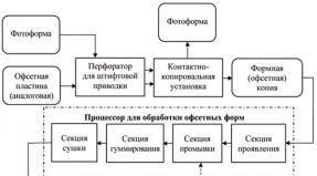
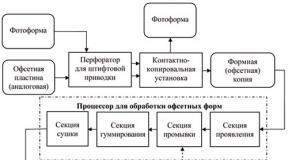
Use a 12-220V converter at home. High voltage and more. Assembly from UPS
A fairly powerful and simple push-pull voltage converter can be built using just two powerful field-effect transistors. I have repeatedly used such an inverter in a variety of designs. The circuit uses two powerful N-channel transistors; it is advisable to take them with an operating voltage of 100 Volts, a permissible current of 40 Amps or more.
The scheme is quite popular on the Internet.
In addition to transistors in the circuit, we have ultra-fast diodes; you can use diodes such as UF4007, HER207, HER307, HER308, MUR460 and others. Two 12-volt zener diodes to limit the voltage on the gates of field switches; it is advisable to take zener diodes with a power of 1 or 1.5 watts; if 12-volt zener diodes are not available, then you can use them with a stabilization voltage of 9-15 volts, not critical.
It is advisable to take limiting resistors with a power of 0.5 or 1 watt; slight overheating of these resistors is possible. The transformer can be wound on the core from a computer power supply, you can even not wind anything, and use the transformer in the opposite way - as a step-up one. Just in case, I will say that the primary or power winding consists of 2x5 turns, wound with a busbar of 5 separate wires of 0.7 mm each (each busbar), the wire is not critical.

The secondary, step-up winding is wound on top of the primary and consists of 45 turns - this is quite enough to produce 220 Volts, taking into account the operating frequency of the generator.
The circuit does not contain critical components, the spread of the element base is quite wide. The transistors must be installed on the heat sink; do not forget to separate them from the heat sink with mica spacers, but this is in the case of one solid heat sink.

The choke can be wound on a ring from the output chokes of a computer power supply; the winding is wound with a busbar of 3 strands of 1 mm wire (each), the number of turns is from 6 to 12.
A little about power and safety measures. The output voltage depends on the connected load; this inverter is designed to work with passive loads (lamp, soldering iron, etc.) since the output frequency is hundreds of times higher than the network frequency.
To connect active loads to the inverter, the voltage from the output of the transformer must first be rectified, then smoothed with an electrolytic capacitor; do not forget that the rectifier must use fast diodes with a reverse voltage of at least 600 volts and a current of 2 Amperes or more. Electrolytic capacitor for voltage 400 Volts, capacity 47-330 µF. The inverter power is 300 watts!
Be extremely careful– the output voltage after the rectifier with a capacitor is deadly!
Voltage for motorists, since in a car it may very often be necessary to obtain mains voltage. This converter can be used to power soldering irons, incandescent lamps, coffee makers and other devices that are powered from a 220 Volt network. The converter can also power active loads - a TV or DVD player, but it is worth noting that this is quite dangerous, since the operating frequency of the converter is quite different from the network 50 Hertz. But, as you know, these devices are equipped with switching power supplies, where the mains voltage is rectified by diodes. These diodes can rectify high frequency current, but I must note that not all pulse units can have such diodes, so it’s better not to risk it. Such a DC-AC voltage converter can be assembled in a couple of hours if you have the necessary components on hand. A scaled-down diagram is shown in the figure:
Transformer is the power component of such a converter. It is wound on a ring of ferrite, which was removed from a Chinese power supply unit for halogen lamps (power 60 watts).

The primary winding of the transformer was wound with 7 wires. To wind both windings, a wire with a diameter of 0.5-0.6 mm was used. The primary winding consists of 10 turns tapped from the middle, i.e. two equal halves of 5 turns each. The windings are stretched across the entire ring. After winding, it is advisable to insulate the windings and wind them with a step-up winding.

The secondary winding consists of 80 turns (the same wire was used as for winding the primary winding). The transistors were installed on heat sinks, but do not forget to insulate them using special gaskets and washers. This is done only when both transistors have a common heat sink.

The choke can be removed and the power connected directly. It consists of 7-10 turns of 1mm wire. The inductor can be wound on a ring made of powdered iron (such rings can easily be found in computer power supplies). The 12-220V inverter circuit does not require preliminary adjustment and works immediately.

The operation is quite stable, thanks to the additional driver, the chip does not heat up. The transistors heat up within normal limits, but I advise you to choose a larger heat sink for them.

The installation is carried out in a housing from an electronic transformer, which plays the role of a heat sink for field switches.
Comments (41):
#1 Snow White February 19 2015
Perfetto. Excellent This circuit seems to be what I was looking for about the transistor, very interesting. If you increase the number of turns, say three times, the current on KT 817 will also drop to 0.6. It doesn't work fast enough, is this the reason for the high current?
To be honest, I haven’t tried to increase the turns. As for the performance speed, yes, that’s why it was replaced with KT940. the current can be reduced further. From the lamp, take only the lamp itself and throw the board out of it. then the current is in the range of 0.3-0.35A..
#3 Selyuk May 12 2015
Everything is very “simple”, but where can I get the transformer cups??
#4 root May 12 2015
In the transformer design of this high-voltage converter there is no gap between the ferrite cups, so you can try using a ferrite ring or frame from a pulse transformer with a ferrite core (you can take it from a non-working computer power supply).
You will need to experiment with the number of turns and output voltage.
#5 pavel June 01 2015
What is the principle for calculating a transformer and selecting transistors for this inverter? I would like to make one with a power supply of 60 volts.
The cups were taken because they were just there, and the number of turns in such a core is needed less. I haven’t tried ferrite rings; it works fine on regular W-shaped ferrite. I don’t remember how many turns I wound, the primary one seemed to be 12 turns with 0.5mm wire, and the booster one was done by eye until the frame on the core was filled. The transformer was taken from a 4 by 5 cm monitor.
#7 Egor October 05 2015
I have a question for you: how many ohms is the resistor on the left at 220???
I'm just not very good at electronics)))
#8 root October 05 2015
If there are only numbers next to the resistor, that means the resistance is in Ohms. In the diagram, the resistor has a resistance of 220 ohms.
Tell me, is it possible to use your circuit to power the MTX-90 thyratron and not from 12, but from a 3.7 volt battery?
If possible, what are the best transistors to use? The MTX-90 has a small operating current - from 2 to 7 mA, and the voltage for ignition needs about 170 volts, well, you can experiment with this with a transformer (about voltage).
I don’t even know what to answer. Somehow I didn’t think about it.. Why do you need to power the thyratron from this circuit? In principle, it will work, of course, the only question is how... from 3.7 volts it is also possible, but the windings must be recalculated or selected experimentally.
#11 Oleg December 13 2015
People, tell us how to make an inverter from transistors from a Chinese typewriter on a control panel. Is it possible to install a ring ferrite core and is it possible to make a 3-fold difference in turns? I should make an inverter this way just for fun and to make it easier. And is it possible to set the input voltage to somewhere around 3V?
Please answer! I will be glad if you answer all my questions! I'm waiting for your answers!
#12 Alexander December 17 2015
I have 30/10 ferrite cups, is it possible to wind a trans on them and what number of turns should be wound, at least approximately.
#13 Alexander January 24 2016
Everything works great there, both the 15 watt lamp and the 20 watt one. More powerful transistors are simply needed. KT940 can be left alone, but 814 could at least be replaced with KT837. And if the current is high, you don’t need to rewind anything, you just need to increase the value of the resistor to 3.1k. And the transformer is not necessarily of this size, even a pulse generator will work from charging, transistors will still play a special role. p.s. These transistors have a power of no more than 10 watts
#14 Eduard February 01 2016
What kind of transistor can I replace KT814 with? Can I use 13005 or KT805?
#15 Alexander February 03 2016
Change it to KT805 - you'll scrape off a lot of power, because according to the datasheet, KT805 can give up to 60 watts
KT814 is p-n-p conductivity, and KT805 and 13005 are n-p-n..., of course you can’t Eduard...
#17 Mars May 11 2016
Instead of KT814 I installed KT816.15W lamp pulled.
#18 sasha November 06 2016
I installed KT805 and KT837. primary 16v.0.5mm. secondary 230v. 0.3mm. lamp 23W. glows great.
#19 Eduard November 19 2016
March. counter question, what then can replace the KT940, so that the KT814 can be replaced with KT805 or 13005 and change the power polarity? An idea arose: I removed the 12-volt pulse transformer from the electronic transformer for halogen lamps, there is just a secondary of 12-14 turns and The primary is about 150-200 turns. If you deploy it as a booster and plug it into this circuit? I think it should work, but if you replace the combination of KT814 and KT940 with something more modern, then you can squeeze out up to 40 W of power? I also want to try it on the UC3845 PWM controller , the circuit there is generally primitive: a UC3845 microcircuit, in its circuit a frequency-setting resistor and a film capacitor, an IRFZ44 field-effect transistor and a transformer from an electronic transformer included in the circuit as a step-up, as a result we have up to 100 W of power at 12 volts
and why "..940 volts in the old colors in abundance.. everyone has nowhere to put it... replace it with any reverse transistor, but you want 805, then yes..940 on forward conduction.... and change the polarity... but again -why do everyone have so many of these in their bins...
#21 pavel February 09 2017
why do you need to increase the power of the circuit :)? What, will you use KrAZ batteries (190 a/h)?? this circuit makes sense, as a friend correctly said, if you use a bulb from a lamp with a burnt-out circuit. Otherwise, to hell with the button accordion: an LED lamp from the same battery, with the same light output, will illuminate many times longer!..
#22 pavel February 09 2017
Now about the transistors: you can change them, but you need to remember that any power transistor provides its declared power only when using an appropriate heat sink. this fact directly affects the dimensions of the entire device. and where will you get energy saving? l ampu more powerful than 30 watts = 150? I haven't seen it on sale. and I already talked about the battery for such a “pacifier” :). so, know your limits, inventors, good luck!
#23 Eduard February 24 2017
March, I just have a problem with the Soviet KT940 and KT814. Basically in my reserves I have imported powerful high-frequency bipolar transistors 13005 for 5 amperes 400 volts, and the like. They managed to light the flask at full brightness from a 30 W energy-saving device, while the transistor was slightly warm. And the Soviet KT814 and KT805 ARE GLUGGY BY THEMSELVES BOIL QUICKLY EVEN WITH A RADIATOR
I would not say that the KT805 is buggy... depending on which one you use. in plastic they are unreliable, there is such a thing, and then for some 80 years. take 805 in metal, it’s generally an indestructible transistor. However, it is necessary to emphasize the fact that they are buggy not because they are bad, but because they did not fall into entirely capable hands, just
But you can even install imported microwave transistors, it will work!!! verified!!. In this article, I wasn’t trying to create a miniature lamp, but rather how to fix a burnt-out lamp at minimal cost. to serve again
the 814 collector should be grounded through a 10 µF capacitor, otherwise when switching the surge is very large.
The 814 transistor is in a half-open state - however, it needs a radiator.
It was easier to use a blocking generator.
what other 10 microfarad capacitor, what nonsense, is it really not clear from the photo that the miniature radiator will all fit into a pack of cigarettes. and using a blocking generator is no easier. there you need at least three windings. and the transistor will heat up there no less!!!
#28 IamJiva August 14 2017
blocking generator serves the same purpose, to provide feedback (bring the microphone to the speaker so that it buzzes), if you did without a microphone, why don’t you need it, here you got by adding a transistor, in blocking you can get by with one transistor, and turn the phase around with turns of the winding, which (allow ) can be independently connected in any polarity. You can squeeze out a lot of watts, but it’s difficult, part of the energy (for powerful lamps is significant, up to 90%) is lost on the diode bridge and electrolyte (in the lamp rectifier) that are cheap (especially if powerful) and 50Hz are suitable, at 50kHz smoke can already come from them and the voltage never appears to start the lamp, 50Hz diodes (simple, that is, not ultrafast or Schottky) do not have time to lock, and drain the charge back into the winding or somewhere else, this causes heating of everything and incorrect operation of the generator, the electrolyte has inductance (series) , and a short pulse it only “recognizes” but is in no hurry to carry out the order, while waiting for the command to set it aside... the current begins to increase to infinity or as long as they give, for 50Hz instantly, for 50kHz - never... the transistor needs to be fast, it can get warm and NO way, IRF840 2 pcs correctly used provided on 4 4 ohm columns of 500wt each, 2000 Wt power in class D powered by +-85V (170V) TL494 PWM, Ir2112 driver in the gates, 4 pcs ultrafast diodes shunt the SI and IC, varistors 400V BC 30V SI
2kW drum and bass power, they were a little warm on the same radiators as here, at the output there is a choke from the fuel assembly and 200 turns, at 2500wt they burned out without warning
It would be a good idea to bypass the output transformer of the primary with a diode, or better yet with a varistor (from flyback impulses possible in the event of a load disconnection, the selection of transistors and turns of the primary for maximum efficiency is as important and valuable as the ratio of sugar and vinegar with water + time on the timer in the microwave, so go away and take out the lollipops, the circuit works like a juggler you’ve never seen, they hope for the ease of transferring the ideal-harmony-efficiency-power to another circus and there’s no need for a jacket
One question for the author. This converter will pull an electric razor from Kharkov, Agidel, Berdsk, etc.
I need just such a miniature one that I can always build it into my shaving machine.
Just don’t write that there are plenty of battery-powered and wind-up electric shavers on sale. My dear to me.
She's been with me half my life.
Good luck.
#30 root January 21 2018
To power a 220V electric razor from the car's on-board network, it is better to assemble some more reliable and powerful voltage converter. Here are a few similar schemes:
- Voltage inverter 12V to 220V from available parts (555, K561IE8, MJ3001)
- Simple voltage inverter 13V-220V for car (CD4093, IRF530)
Thanks for the links, but it’s too expensive and difficult to assemble on your knees.
I don't have such details. But the old color.tel. and there is a tape recorder. It's all there
People write that you can increase the power by replacing transistors with 805.837.
An electric razor consumes 30 watts. Maybe it will. What do you think?
I came across the Variom A ROM.
The trouble is that the P216G transistors can no longer be found, and one of them is not working. According to the parameters, the GT701A seems to be suitable, but here’s how to determine the resistors. There are only 4 of them, two pairs. I don’t think it will work just replacing both P216Gs with GT701A. Tell.
#33 root February 05 2018
Agu1954, P216 transistors can be replaced with GT701A or P210V. Below are the main operating limits of these transistors:
- P216G: Ukb, max=50V; Ik max=7.5A; Pk max=24W; h21e>5; f gr.>0.2 MHz;
- P210V: Ukb, max=45V; Ik max=12A; Pk max=45W; h21e>10; f gr.>0.1 MHz;
- GT701A: Ukb, max=55V; Ik max=12A; Pk max=50W; h21e>10; f gp.=0.05 MHz;
Replace two transistors P216 with GT701A (P210V). For safety reasons, the first connection of the circuit to the battery is made through a 3A fuse.
P.S. Please ask questions not related to the diagram given in the publication on the forum or in our social groups VK and FB.
#34 Sergey February 16 2018
#35 root February 16, 2018
Hello, Sergey. An old, and no longer working, postal address was indicated. Fixed it with a new one.
#36 Sergey February 16 2018
This converter operates at a frequency far greater than 50Hz. somewhere in the region of 20-50 kHz. Even if you increase the power by replacing transistors with more powerful ones, the razor will still not work. the engine simply cannot physically operate at a frequency of tens of kilohertz
#38 Petro Kopitonenko November 19 2018
To lower the frequency of the current on the converter, you must try to increase the number of turns of the transformer, both the primary and secondary windings. Where am I coming from? 50 hertz transformers have a large number of turns. And high-frequency ones have a small number of turns. This is the same as in oscillatory circuits, the frequency depends on the number of turns. I soldered an experimental converter with a factory transformer at 50 hertz. There, two primary windings are wound with 40 turns instead of 10 turns according to the circuit. I could hear the transformer humming at a frequency of about 40 hertz by ear. If it was a frequency of 50 kilohertz, I would not hear anything!!!
#39 David June 13 2019
Or you can use a ready-made transformer in this circuit. For example, step-up transformer TP 30-2, just connect in reverse (to the 15 volt output winding)
#40 root June 15 2019
The circuit requires a high-frequency transformer; TP 30-2 or another network transformer with Sh-like or toroidal iron will not work here.
#41 Dmitry October 06 2019
Good day! The primary of the transformer must be equipped with a snubber. With the second transistor you are practically switching the inductance. And don’t care that the voltage is low! With a snubber chain it will be easier for transistors. Someone above already suggested shunting the 814 collector with a capacitance, but it went unheard. But better, of course, is a classic snubber - diode, resistor, capacitor.
Car inverters 12-220 are quite suitable devices. With their help, you can get a mains voltage of 220 Volts from the vehicle's on-board 12 Volt network. The device is a DC-AC step-up voltage converter, the output of which produces a voltage of 220 Volts (+/-20 Volts).

Powerful inverters of this kind cost about 100-150 dollars, but at home it is possible to construct a similar converter that will work no worse than the factory one.
So, let's look at the high power converter circuit.

This circuit can power powerful loads up to 1000 watts. The circuit is quite common, but has been modified to increase the output power.
The widely used TL494 microcircuit was used as a master oscillator.


This is a high-precision two-channel PWM controller without an additional driver, so to drive field-effect transistors you need to further amplify the signal from the chip.
The circuit uses only 4 output stages - 4 pairs of powerful field-effect transistors of the IRF3205 series.

During operation under load, the field-effect transistors will heat up, so it is possible that, in addition to heat sinks, they will need a blower.

The transformer is the main (power) part of the circuit. The transformer can be wound on a 65x50x30 ring. You can use cores from BP AT or ATX transformers as a core
See the transformer manufacturing process below...


The primary winding consists of 10 turns with a tap in the middle. Wind the winding like this.
First, prepare the wire for winding. The wire can be taken with a diameter of 0.8-1.2mm, in our case 1mm
We take 12 cores of such a wire with a length of 15 cm. We twist the ends so that the strands stay together and wind 5 turns around the entire frame. We try to wind it evenly; a lot depends on the winding.
Next, we insulate this winding (preferably with fabric insulating tape) and wind exactly the same winding over the first one. Winding is done in the same way, the wire again consists of 12 cores of millimeter wires, the number of turns is also 5.
Next you need to phase the winding. First you need to remove the varnish from the ends of the wires and tin the ends.
We connect the transformer to the circuit. We connect the beginning of the first half with the end of the second, or vice versa - the end of the first with the beginning of the second arm. Thus we will have one winding with a tap from the middle point.
Later, we isolate the primary winding and wind it up.
The winding contains 80 turns. The wire is wound in rows, in my case I wound 5 strands of 0.75mm wire, but you can take a thinner wire. In order for the coils to fit without much effort, it is advisable to wind them on a ring.
The frequency at the output of the device is increased, so I don’t recommend powering active loads with such a converter, although my TV and players with a switching power supply work quite normally, but the music center refused to work, the reason is that there is a 50Hz network transformer inside, which cannot work at such a frequency.
The inverter can power irons, incandescent lamps, space heaters, soldering irons and more. Thanks to pulse technology, the dimensions of the device are quite compact. Such a converter used to power a car amplifier; you just need to rewind the step-up winding and you will have a pretty decent converter from 12 to 220 Volts with high output power.; Field keys can be replaced with similar ones, the choice is large IRF2505, and IRL3205, IRFZ44, IRFZ48 (with the last two, the power will decrease to 700-800 watts)
I am already planning to assemble a converter with an output power of 1800-2000 watts and wound up a transformer, below are photographs of the ring used (dimensions - 65x50x30). For our purposes, we need to use 2000 NM rings.
Buying a ready-made device will not be a problem– in auto stores you can find (pulse voltage converters) of various powers and prices.
However, the price of such a medium-power device (300-500 W) is several thousand rubles, and the reliability of many Chinese inverters is quite controversial. Making a simple converter with your own hands is not only a way to significantly save money, but also an opportunity to improve your knowledge in electronics. In case of failure, repairing a homemade circuit will be much easier.
Simple pulse converter
The circuit of this device is very simple, and most parts can be removed from an unnecessary computer power supply. Of course, it also has a noticeable drawback - the 220 volt voltage obtained at the output of the transformer is far from sinusoidal in shape and has a frequency significantly higher than the accepted 50 Hz. Electric motors or sensitive electronics must not be connected directly to it.

In order to be able to connect equipment containing switching power supplies (for example, a laptop power supply) to this inverter, an interesting solution was used - A rectifier with smoothing capacitors is installed at the output of the transformer. True, the connected adapter can only work in one position of the socket, when the polarity of the output voltage coincides with the direction of the rectifier built into the adapter. Simple consumers such as incandescent lamps or a soldering iron can be connected directly to the output of transformer TR1.
The basis of the above circuit is the TL494 PWM controller, the most common in such devices. The operating frequency of the converter is set by resistor R1 and capacitor C2; their values can be taken slightly different from those indicated without noticeable changes in the operation of the circuit.
For greater efficiency, the converter circuit includes two arms on power field-effect transistors Q1 and Q2. These transistors should be placed on aluminum radiators; if you intend to use a common radiator, install the transistors through insulating spacers. Instead of the IRFZ44 indicated in the diagram, you can use IRFZ46 or IRFZ48 that are similar in parameters.
The output choke is wound on a ferrite ring from the choke, also removed from the computer power supply. The primary winding is wound with a wire with a diameter of 0.6 mm and has 10 turns with a tap from the middle. A secondary winding containing 80 turns is wound on top of it. You can also take an output transformer from a broken uninterruptible power supply.
Read also: We talk about the design of a welding transformer
Instead of high-frequency diodes D1 and D2, you can take diodes of types FR107, FR207.
Since the circuit is very simple, once turned on and installed correctly, it will start working immediately and will not require any configuration. It will be able to supply a current of up to 2.5 A to the load, but the optimal operating mode will be a current of no more than 1.5 A - and this is more than 300 W of power.
Ready-made inverter of such power would cost about three to four thousand rubles.This scheme is made with domestic components and is quite old, but this does not make it any less effective. Its main advantage is the output of full alternating current with a voltage of 220 volts and a frequency of 50 Hz.

Here the oscillation generator is made on the K561TM2 microcircuit, which is a dual D-trigger. It is a complete analogue of the foreign CD4013 microcircuit and can be replaced by it without changes in the circuit.
The converter also has two power arms based on KT827A bipolar transistors. Their main disadvantage compared to modern field ones is their higher resistance in the open state, which is why they heat up more for the same switched power.
Since the inverter operates at low frequency, the transformer must have a powerful steel core. The author of the diagram suggests using the common Soviet network transformer TS-180.
Like other inverters based on simple PWM circuits, this converter has an output voltage waveform quite different from the sinusoidal one, but this is somewhat smoothed out by the large inductance of the transformer windings and the output capacitor C7. Also, because of this, the transformer may emit a noticeable hum during operation - this is not a sign of a circuit malfunction.
Simple transistor inverter
This converter works on the same principle as the circuits listed above, but the square-wave generator (multivibrator) in it is built on bipolar transistors.

The peculiarity of this circuit is that it remains operational even on a heavily discharged battery: the input voltage range is 3.5...18 volts. But, since it does not have any stabilization of the output voltage, when the battery is discharged, the load voltage will simultaneously drop proportionally.
Since this circuit is also low-frequency, a transformer will be required similar to that used in the inverter based on K561TM2.
Improvements to inverter circuits
The devices presented in the article are extremely simple and have a number of functions. cannot compare with factory analogues. To improve their characteristics, you can resort to simple modifications, which will also allow you to better understand the principles of operation of pulse converters.
Read also: We make a semi-automatic welding machine with our own hands
Increased power output
All described devices operate on the same principle: through a key element (arm output transistor), the primary winding of the transformer is connected to the power input for a time specified by the frequency and duty cycle of the master oscillator. In this case, magnetic field pulses are generated, exciting common-mode pulses in the secondary winding of the transformer with a voltage equal to the voltage in the primary winding multiplied by the ratio of the number of turns in the windings.
Therefore, the current flowing through the output transistor is equal to the load current multiplied by the inverse turns ratio (transformation ratio). It is the maximum current that the transistor can pass through itself that determines the maximum power of the converter.
There are two ways to increase the power of the inverter: either use a more powerful transistor, or use parallel connection of several less powerful transistors in one arm. For a homemade converter, the second method is preferable, since it not only allows you to use cheaper parts, but also preserves the functionality of the converter if one of the transistors fails. In the absence of built-in overload protection, such a solution will significantly increase the reliability of a homemade device. The heating of the transistors will also decrease when they operate at the same load.
Using the last diagram as an example, it will look like this:

Automatic shutdown when battery is low
The absence in the converter circuit of a device that automatically turns it off when the supply voltage drops critically, can seriously let you down, if you leave such an inverter connected to the car battery. Supplementing a homemade inverter with automatic control will be extremely useful.
The simplest automatic load switch can be made from a car relay:

As you know, each relay has a certain voltage at which its contacts close. By selecting the resistance of resistor R1 (it will be about 10% of the resistance of the relay winding) you adjust the moment when the relay opens its contacts and stops supplying current to the inverter.
EXAMPLE: Let's take a relay with an operating voltage (U p) 9 volts and winding resistance (R o) 330 ohm. So that it works at a voltage above 11 volts (U min), a resistor with resistance must be connected in series with the windingR n, calculated from the condition of equalityU r /R o =(U min —U p)/R n. In our case, we will need a 73 ohm resistor, the nearest standard value is 68 ohms.Of course, this device is extremely primitive and is more of a workout for the mind. For more stable operation, it needs to be supplemented with a simple control circuit that maintains the shutdown threshold much more accurately: