Course work: Comparative analysis of the technology for manufacturing printing plates for flexographic printing. Technologies for manufacturing offset printing plates History of the development of flexographic printing
Introduction
1. Main types of plates for offset printing
1.1 Offset printing method
1.2 Methods for producing printing plates and types of plates
2. Analog plate materials
2.1. Form materials for the production of printed forms by contact copying
2.1.1 Bimetallic strips
2.1.2 Monometallic plates
2.2 Electrostatic plate materials
3. Digital plate materials
3.1 Paper plates
3.2 Polyester plates
3.3 Metal plates
3.3.1 Silver-containing plates
3.3.2 Photopolymer plates
3.3.3 Thermal plates
3.3.4 Processless plates
3.3.5 Hybrid plates
4. Form plates for offset printing without humidification
4.1 Plates for dry offset
4.2 Pros and cons of “waterless” plates
Conclusion
References
Applications
Appendix 1
Appendix 2
Appendix 3
Appendix 4
Appendix 5
Introduction
Today, despite the variety of methods for producing printed products, the flat offset printing method remains dominant. This is due, first of all, to the high quality of prints due to the ability to reproduce images with high resolution and identical quality of any areas of the image; with the comparative simplicity of obtaining printed forms, allowing to automate the process of their production; with ease of proofreading, with the ability to obtain large-sized prints; with a small mass of printed forms; with a relatively inexpensive cost of molds. UK Printing Information Research Association PIRA predicts that 2010 will be the year of offset printing, with a market share of 40 percent, surpassing all other printing processes.
Rationalization continues in the area of offset prepress processes, with the goals of reducing production times and merging with printing processes. Reproduction companies are increasingly preparing digital data that is transferred to the printing plate or directly to the press. Technologies for direct exposure to plate materials are actively developing, while information processing formats are increasing.
The most important element of offset printing technology is the printing plate, which has undergone significant changes in recent years. The idea of recording information on printed material not by copying, but by line-by-line recording, first from a material original and then from digital data sets, was known already about thirty years ago, but its intensive technical implementation began relatively recently. And although it is impossible to switch to this process immediately, such a transition is gradually taking place. However, there are also enterprises (and not only in our country) that still work the old fashioned way, and treat modern materials with suspicion, despite the fact that these plates are manufactured with the highest specified quality and have all the manufacturer’s guarantees. Therefore, along with a wide range of offset plates for laser recording, there are also conventional copy plates, which in many cases are recommended by manufacturers at the same time for recording by laser scanning or laser diode.
This paper examines the main types of plates for the traditional technology of producing offset printing plates, which involves copying an image from a photoform onto a plate in a copy frame and subsequent development of the offset copy manually or using a processor, and then for the computer-printing plate technology ( Computer-to-Plate), let's call it CtP for short. The latter allows you to expose an image directly onto a plate without using photoforms. The main focus will be on CtP plates.
The basic terms of printing production mentioned in the work are given in the appendix (see appendix 1).
1.1 Offset printing method
The offset printing method has existed for more than a hundred years and today is a perfect technological process that provides the highest quality of printed products among all industrial printing methods.
Offset printing (from the English offset) is a type of flat printing in which ink from the printing plate is transferred to the rubber surface of the main offset cylinder, and from it is transferred to paper (or other material); this allows thin layers of ink to be printed on rough papers. Printing is done from specially prepared offset forms, which are loaded into a printing machine. Currently, two methods of flatbed printing are used: offset with moisture and offset without moisture (“dry offset”).
In wet offset printing, the printing and blank elements of the printing plate lie in the same plane. Printing elements have hydrophobic properties, i.e. the ability to repel water, and at the same time oleophilic properties, allowing them to accept paint. At the same time, the blank (non-printing) elements of the printing form, on the contrary, have hydrophilic and oleophobic properties, due to which they perceive water and repel ink. The printing plate used in offset printing is a ready-to-print plate that is mounted on a printing press. An offset printing machine has groups of rollers and cylinders. One set of rollers and cylinders applies a water-based dampening solution to the printing plate, while the other applies an oil-based ink (Figure 1). The printing plate, placed on the surface of the cylinder, is in contact with the roller systems.
Rice. 1. Main components of the offset printing unit
Water or a dampening solution is perceived only by the whitespace elements of the form, and oil-based ink is perceived by the printing elements. The ink image is then transferred to an intermediate cylinder (called a blanket cylinder). The transfer of the image from the offset cylinder to paper is ensured by creating a certain pressure between the printing and offset cylinders. Thus, flat-plate offset printing is a printing process based solely on the principle that water and printing ink, due to their physical and chemical differences, repel each other.
Offset without humidification uses the same principle, but with different combinations of surfaces and materials. Thus, an offset printing plate without moisture has blank areas that strongly repel ink due to the silicone layer. Ink is perceived only in those areas of the printing plate from which it has been removed.
Today, a large number of different plate materials are used to produce flat offset printing plates, which differ from each other in manufacturing method, quality and cost. They can be obtained in two ways - formatted and element-by-element notation. Format notation– this is recording an image over the entire area at the same time (photography, copying), the so-called traditional technology. Printing forms can be made by copying from photographic forms - transparencies - positive way of copying or negatives - negative copying method. In this case, plates with a positive or negative copy layer are used.
At element-by-element notation The image area is divided into some discrete elements, which are recorded gradually element by element (recording using laser radiation). The last method of producing printed forms is called “digital”, it involves the use of laser exposure. Printing plates are produced in direct printing systems or directly in a printing machine (Computer-to-Plate, Computer-to-Press).
So, CtP is a computer-controlled process for making a printing plate by directly recording an image on the plate material. At the same time, there are completely no intermediate material semi-finished products: photo forms, reproduced original layouts, montages, etc.
Each printed form recorded digitally is the first original copy, which provides the following indicators:
Greater sharpness of points;
More accurate registration;
More accurate reproduction of the gradation range of the original image;
Less dot gain during printing;
Reducing the time for preparatory and adjustment work on the printing machine.
The main problems of using CtP technology are problems with initial investments, increased requirements for operator qualifications (in particular, retraining), organizational problems (for example, the need to launch ready-made runs).
So, depending on the method of manufacturing printing forms, they distinguish analog And digital plates.
There are also plates such as Waterless (dry offset), which will be mentioned in my work.
Let's take a closer look at the main types of plates for offset printing and their technical characteristics.
Technologies for manufacturing offset printing plates
Yuri Samarin, Dr. tech. sciences, prof. MSUP im. Ivan Fedorov
In modern prepress processes, three technologies are mainly used for the production of offset printing plates: “computer-to-film”; “Computer-to-Plate” and “Computer-to-Press”.
The process of manufacturing offset printing plates using computer-photoform technology (Fig. 1) includes the following operations:
- punching holes for pin register on the photoform and plate using a puncher;
- formatted recording of an image on a plate by exposing the photoform on a contact-copying machine;
- processing (developing, washing, applying a protective coating, drying) of exposed plate copies in a processor or production line for processing offset plates;
- quality control and technical proofreading (if necessary) of printed forms on a table or conveyor to review forms and correct them;
- additional processing (washing, applying a protective layer, drying) of forms in the processor;
- heat treatment of molds in a firing oven (if necessary, increasing run resistance).

Rice. 1. Scheme of the process of manufacturing offset plates using the “computer-photoform” technology
The quality of photoforms must meet the requirements of the technological process for manufacturing printing plates. These requirements are determined by the printing method, technology and materials used. For example, a set of color-separated raster slide photo forms for sheet-fed offset printing on a multicolor machine (printing on wet) on the most common coated paper today should have the following characteristics:
- absence of scratches, creases, foreign inclusions and other mechanical damage;
- minimum optical density (optical density of the film base taking into account the density of the veil) - no more than 0.1 D;
- the maximum optical density for photoforms made by laser exposure (taking into account the density of the veil) is not less than 3.6 D;
- raster dot core density is at least 2.5 D;
- the minimum value of the relative area of raster elements is no more than 3%;
- presence of paint names on the photo form;
- the angles of inclination of the raster structure correspond to the specified values for each paint;
- the lineature of the raster structure corresponds to the specified one;
- misalignment of images on photoforms of one set along crosses - no more than 0.02% of the diagonal length. This value takes into account repeatability tolerances during laser exposure and the amount of film deformation;
- presence of control marks and scales on the photo form.
A photoform of a full-size printed sheet can be obtained either directly by outputting an image in a photooutput device of the appropriate format, or by assembling individual strips from photoforms. In this case, installation is carried out manually on the assembly table.
Forms of offset flat-bed printing on blank and printing elements have different physical and chemical properties in relation to printing ink and wetting agent. The whitespace elements form hydrophilic surfaces that perceive moisture, and the printing elements form hydrophobic areas that perceive printing ink. Hydrophilic and hydrophobic areas are created during the processing of the plate material.
Forms of offset flatbed printing can be divided into two main groups: monometallic and polymetallic - depending on what is used to create whitespace and printing elements - one metal (monometal) or several (polymetal). Currently, polymetallic molds are practically not used. With all modern methods of manufacturing monometallic forms, hydrophobic printing elements are created on films of the copy layer, firmly adhered to the developed surface of the metal, and blank elements are created on adsorption hydrophilic films formed on the surface of the base metal.

Rice. 2. Methods of contact copying: a - positive; b - negative. 1 - substrate; 2 - copy layer; 3 — photographic slide; 4 - negative photoform
Offset printing plates are made using negative or positive contact copying methods (Fig. 2). In the negative method, negatives are copied onto a photosensitive copy layer, and in this case, the hardened copy layer serves as the basis for the printing elements. With the positive method, a photosensitive layer is copied from a slide, and then the exposed areas are dissolved when the copy is processed.
The positive copying method ensures greater accuracy in the transfer of image elements and stability of the printing elements during the printing process.
For the production of offset forms, centrally produced pre-sensitized positive or negative offset plates are used.
Pre-sensitized positive plates are a multilayer structure (Fig. 3). They are produced from highly pure rolled aluminum and are the result of a complex and lengthy process that guarantees a high quality product. These plates are designed for the production of high-quality offset plates for sheet-fed and web presses using the positive copy method.

Rice. 3. Structure of the positive offset plate: 1 - aluminum base; 2 — electrochemical granulation; 3 - oxide film; 4 - hydrophilic sublayer; 5 - photosensitive copy layer; 6 - micropigmented layer
After electrochemical treatment, oxidation and anodization, the aluminum base acquires physical and chemical characteristics that ensure high resolution and circulation resistance, stability of the hydrophilic properties of space elements on an offset printing plate, uniform distribution of the ink layer and moisturizing solution over the entire area of the plate.
After exposure, a good representation of the color of the copy layer is provided, allowing you to control the copy quality before development. The printing elements formed by the copy layer have a good contrast compared to the white-space areas, which allows the plates to be used for scanning in automatic monitoring and control systems for offset printing. During the printing process, thanks to the developed capillary structure of the anodized layer, the optimal ink-water balance is quickly established, which is stably maintained during the printing process. The copy printing layer is characterized by high resistance to the action of alcohol-based moisturizing solutions and washing materials. The oxide layer strengthens the gap areas and increases the circulation resistance of printing forms, protecting their surfaces from scratches and abrasion. The high-quality aluminum base ensures a tight fit to the plate cylinder and ensures that the mold is resistant to fracture.
High photosensitivity and photo-width of the copy layer can reduce exposure time, ensure accurate reproduction and simplify the development process.
Micropigmentation (vacuum coating) of the copy layer promotes close contact with the photo form during exposure and rapid creation of a vacuum.
The main technical indicators of positive (analog) plates have approximately the following values:
- roughness - 0.4-0.8 microns;
- thickness of the anodized layer - 0.8-1.7 microns;
- thickness of the copy layer - 1.9-2.3 microns;
- spectral sensitivity - 320-450 nm;
- energy sensitivity - 180-240 mJ/cm2;
- exposure time (at illumination of 10,000 lux) - 2-3 minutes;
- the minimum size of reproducible strokes is 6-8 microns;
- raster image lineature - 60 lines/cm (150 lpi);
- gradation of raster elements - 1-2% in highlights, 98-99% in shadows;
- circulation resistance - up to 150 thousand prints without heat treatment and up to 1 million prints with heat treatment;
- copy layer color - blue, green, dark blue;
- plate thickness - 0.15; 0.2; 0.3; 0.4 mm.
Printing forms must have pin holes of different configurations (round, oval, rectangular) on the leading edge. Pin (registration) holes facilitate the registration of images obtained when printing from ready-made printing plates.
Before copying, photoforms and plates are placed on the pins of a special ruler supplied with the puncher using register holes. The configuration, number of holes and the distance between them (Fig. 4) depend on the print format and the adopted registration standard, which must correspond to the pin ruler of the printing machine. The finished form is placed on the appropriate pins in the printing machine.

Rice. 4. Printing form with pin holes: L – image field format; S—leading edge of the mold; D - distance between grooves
To punch pin holes in photoforms and plates, special devices are used - manual or pedal-driven punchers.
Before exposure, it is necessary to carefully prepare the glass of the copy frame - clean it from dirt and dust using special means.
The plate is placed in a copy frame and a mounting of photoforms is placed on it with an emulsion layer to the copy layer of the plate. The combination of the plate and the mounting is carried out using pins located on a special ruler. The image on the plate must be readable.
In the absence of a pin register system, the copier measures the specified valve size with a ruler on both sides (the distance from the cutting marks of the installation to the edge of the plate) and secures the installation with adhesive tape.
Behind the cropped image field, the SPSh-K, RSh-F copying process control scales or the Ugra-82 control scale are installed.
For exposure, it is necessary to ensure full contact between the mounting of the transparencies and the surface of the plate, which is achieved through a two-stage vacuum in the contact-copying unit.
The exposure mode depends on the type of plate, the power of the illuminator (the illumination of the glass of the copy frame must be at least 10 thousand lux), the distance from the illuminator to the glass of the copy frame, the nature of the slides, and is determined experimentally.
The correctness of the choice of exposure time is assessed by the reproduction of the sensitometric scale on a copy after it has been developed on the form: for test printing, 3-4 fields of the SPS-K scale (optical density 0.45-0.6) must be fully developed, for production printing - 4- 5 fields (optical density 0.6-0.75).
In order to reduce the amount of proofreading to eliminate extraneous images (strokes from the edges of the film during installation, traces of adhesive tape), additional exposure is carried out with a scattering (matted) film. Exposure time with diffuse film is usually 1/3 of the main exposure time.
It should be borne in mind that the use of scattering film does not affect the reproduction of small raster dots and line elements if they have high optical density and contrast. For highly artistic publications, in order to avoid defective copying, the use of scattering film during exposure should be avoided.
For development, the exposed plate is placed on the processor loading table and fed to the transport rollers. Further advancement of the plate occurs automatically.
Depending on the type of processor, development is carried out by jets of solution supplied to the copy from the tank of the development section, or by immersing the copy in a cuvette with a developing solution with the simultaneous mechanical action of a fleecy roller.
The offset copy appears in accordance with the capabilities of the processor at a temperature of 21-25 ° C for 20-35 s. For each type of plate, their manufacturers provide recommendations on the composition and consumption of developer that must be followed.
For manual development, the same developing solutions are used. The process is carried out at a temperature of 21-27 °C. With a small amount of image on the form, the development time is 45-60 s. With a medium and large number of printing elements, it is recommended to first develop the plate for 30-40 s, check and, if necessary, continue development for another 30-40 s. It is recommended to develop the copy using a soft swab. In this case, it is unacceptable for abrasive particles of sediment and undiluted developer concentrate to get on the surface of the plate.
The speed of the offset copy depends on the type of processor, the operating time of the developer and its temperature.
The temperature of the solution in the section is set on the mode setting panel in accordance with the technical parameters of the processor. It is necessary to strictly observe the temperature regime of the developing solution. At a temperature below the recommended one, incomplete removal of the copy layer from the white space areas is possible, which during printing will lead to a “shadowing” effect on the form. Temperatures higher than recommended make the developer more aggressive, which can damage the printing elements and reduce the print run life of the printing plates.
As the developing solution becomes depleted, it must be adjusted with fresh portions and then completely replaced. Modern processors have a system for constantly replenishing the developer. For this purpose, a container with regenerate is provided, from where fresh portions of the regenerated developer are supplied to the development section after passing through each form.
Washing is carried out automatically in the jetting section in the washing section. Excess water on the mold is squeezed out by rollers at the exit from the section.
The application of a protective coating (gumming) to the mold is carried out automatically using a roller method, followed by pressing at the exit from the section. Rollers for applying protective coating must be thoroughly washed with water before starting work.
Drying is carried out by blowing the mold using fans with air heated to 40-60 °C when passing through the drying section. To control quality, the finished form is transferred to the proofing table and carefully examined. Whitespace elements of the form must be fully developed. All defects of white-space elements: traces of adhesive material, shadows from the edges of the transparencies, excessive marks and crosses, etc. - removed using a “minus” correction pencil or a thin brush moistened with correction gel. Correction is carried out on the protective coating. The copy layer is completely dissolved in the correction composition, so it should be applied very carefully without affecting the image. The time the correction lasts until the layer visually dissolves is 5-10 s.
Defects in printing elements: gaps on the dies, missing parts of the design, etc. - corrected using a “plus” correction pencil: a thin layer of varnish is applied to the missing elements and local heating is carried out to fix it.
The corrected form is subjected to additional processing, for which it is introduced into the washing section of the processor, then a protective coating is applied again and dried. The form is ready!
Heat treatment is carried out in special installations - firing furnaces, consisting of a loading table, a heating cabinet and an unloading table.
Forms intended for heat treatment are necessarily covered with a layer of colloid in order to protect the blank elements from dehydration, and the printing elements from cracking.
The protective coating is applied to clean molds, after first removing the gumming layer from them - manually on a table or in a processor. In the latter case, the colloid is poured into the protective coating section. The mold is placed on the loading table and fed onto transport rollers. Further promotion is carried out automatically.
The temperature and time of heat treatment are set on the mode setting panel: temperature 180-240 °C, time 3-5 minutes. After heat treatment, a visual inspection of the shape is carried out: the image becomes dark, saturated and has the same color throughout the entire format. The colloid layer can serve as a protective coating when storing forms for no more than a day. For long-term storage of forms, it is removed from the surface with warm water using a sponge and a conventional protective coating is applied.
The forms are laid out with sheets of clean paper and stored horizontally on racks in a room with non-actinic lighting, away from heating devices.

Rice. 5. Scheme of the process of manufacturing offset plates using the “computer - printing plate” technology
The process of manufacturing offset printing plates using the computer-printing plate technology (Fig. 5) includes the following operations:
- transfer of a digital file containing data on color-separated images of a full-size printed sheet to a raster processor (RPP);
- automatic loading of the form plate into the forming device;
- processing of a digital file in RIP (reception, interpretation of data, rasterization of an image with a given lineature and raster type);
- element-by-element recording of color separated images of full-size printed sheets on a form plate by exposing it in a forming device;
- processing of the plate copy (developing, washing, applying a protective layer, drying, including, if necessary for some types of plates, preheating the copy) in a processor for processing offset plates;
- quality control and technical proofreading (if necessary) of printed forms on a table or conveyor for viewing forms;
- additional processing (washing, applying a protective layer, drying) of corrected printing forms in the processor;
- heat treatment (if necessary, increasing circulation resistance) of forms in a firing oven;
- punching pin (registration) holes using a punch (if there is no built-in punch in the forming device).
To produce offset printing plates using the computer-printing plate technology, light-sensitive (photopolymer and silver-containing) and heat-sensitive plates (digital) are used, including those that do not require chemical treatment after exposure.
Plates based on a photopolymer layer are sensitive to radiation in the visible part of the spectrum. Wafers for green (532 nm) and violet (410 nm) lasers are currently common. The structure of the plates is as follows (Fig. 6): a layer of monomer is applied to a standard anodized and grained aluminum base, protected from oxidation and polymerization by a special film, which dissolves with water during further processing. Under the influence of light of a given wavelength, polymerization centers are formed in the monomer layer, then the plate is heated, during which the polymerization process accelerates. The resulting latent image is etched with a developer, which washes out the unpolymerized monomer and leaves the polymerized printing elements on the plate. Photopolymer offset plates are designed for exposure in forming devices with a visible light laser - green or violet.

Due to their high exposure speed and ease of processing, these plates are widely used and provide the ability to obtain 2-98% halftone dots with lineatures up to 200 lpi. If they are not subjected to additional heat treatment, the plates can withstand up to 150-300 thousand impressions. After firing - more than a million prints. The energy sensitivity of photopolymer plates ranges from 30 to 100 μJ/cm2. All operations with plates must be carried out under yellow light.
Plates based on a silver-containing emulsion are also sensitive to radiation in the visible part of the spectrum. There are plates for red (650 nm), green (532 nm) and violet (410 nm) lasers. The principle of formation of printing elements is similar to photographic - the difference is that in a photograph, the silver crystals that were hit by light remain in the emulsion, and the rest of the silver is washed out by the fixer, while on the plates, silver from unexposed areas moves to the aluminum substrate and becomes printing elements , and the emulsion, along with the silver remaining in it, is completely washed off.
In recent years, plates that are photosensitive to the violet region of the radiation spectrum (400-430 nm) have become increasingly used. For this reason, many forming devices are equipped with a violet laser. During the exposure of these plates (Fig. 7), a violet laser beam activates silver-containing particles on the space elements. Unexposed areas after processing with developer form printing elements.

During the development process, silver-containing particles are activated, and they form stable bonds with gelatin. Particles that have not been illuminated remain mobile and capable of diffusion.
At the next stage, silver ions that have not been exposed to illumination diffuse from the emulsion layer through the barrier layer onto the surface of the aluminum base, forming printing elements on it.
Once the image is fully formed, the gelatin fraction of the emulsion and the water-soluble barrier layer are completely removed during washing, leaving only the printing elements in the form of deposited silver on the aluminum base.
These plates provide 2-98% dots at 250 lpi, their circulation resistance is 200-350 thousand prints, and their light sensitivity is maximum. The energy sensitivity of the plates ranges from 1.4 to 3 μJ/cm.
Due to the high sensitivity, less time and energy is required to expose the plate. This, in turn, leads to both an increase in the productivity of the forming device and a reduction in laser power consumption and an extension of its service life. As a result of using a thin silver layer, which is more than an order of magnitude thinner than a polymer layer, ink dot gain is reduced, which leads to improved print quality. All operations with plates must be carried out under yellow light. Plates based on silver-containing emulsion are not recommended for printing with UV inks, or for firing.
Heat-sensitive plates have the following structure: a layer of polymer material (thermopolymer) is applied to an aluminum base. Under the influence of IR radiation, the coating is destroyed or changes its physical and chemical properties, as a result, during subsequent chemical processing, blank (in the case of a positive material) or printing (in a negative process) elements are formed. To expose such plates, a laser with a radiation wavelength of 830 or 1064 nm is used.

Rice. 8. Technological process of recording and processing thermoplates: 1 - emulsion layer (thermopolymer); 2 - aluminum substrate; 3 — laser beam; 4 — exposed thermopolymer; 5 - heating element; 6 — printing elements of the form; 7 - developing solution; 8 - printing ink
The resolution of thermally sensitive plates can provide image recording with a line size of up to 330 lpi, which corresponds to obtaining a one-percent dot measuring 4.8 microns. At the same time, the circulation resistance of the resulting printing forms reaches 250 thousand prints without firing and 1 million prints with firing. The processing of these plates after exposure consists of three steps (Fig. 8):
- pre-firing - the surface of the mold is fired for approximately 30 s at a temperature of 130-145 ° C. This process strengthens the printables (so they can't dissolve in the developer) and softens the whitespace. Pre-firing is a mandatory operation;
- development - standard positive developing process: immersion in solution, brushing, washing, gumming and forced air drying;
- firing - after processing, the plate is fired for 2.5 minutes at a temperature of 200 to 220 ° C to ensure its strength and greater durability.
Currently, the Russian market offers a wide range of heat-sensitive plates, including new generation plates that do not require preheating for processing. These plates generally provide 1-99% dots with a screen lineature of 200 lpi, a run resistance of 150 thousand prints without firing, and their light sensitivity varies, ranging from 110 to 200 mJ/cm2.
For chemical treatment of exposed plates, it is recommended to use reagents from the same manufacturer intended for materials of this type. This makes it possible to guarantee the achievement of high technical characteristics potentially inherent in modern mold material.
Plates that do not require chemical treatment after exposure are called processless plates. Currently, two types of mold materials have been developed that do not require chemical treatment: with thermally removable layers (thermoablative) and with layers that change the phase state.
Thermoablation plates are multilayer, and the gap elements in them are formed on the surface of a special hydrophilic or oleophobic layer. During the exposure process, selective thermal removal of a special layer occurs using IR radiation (830 nm). There are positive and negative versions of thermal ablative plates. In negative plates, the oleophobic layer is located above the oleophilic printing layer, and during the exposure process it is ablated from the future printing elements of the form. In positive plates, the opposite is true: above there is an oleophilic printing layer, which is removed during exposure from future blank elements of the form. Combustion products are removed by an exhaust system, which must be equipped with a forming device, and after exposure the plate is washed with water.
Thermoablation mold materials are based on aluminum plates or polyester films.
The disadvantages of processless plates include a higher price and low circulation resistance (about 100 thousand impressions).
In operational printing, in the production of short-run products that do not require high quality (instructions, forms, etc.), offset printing forms on paper and polymer bases are used.
Paper-based offset printing forms can withstand circulations of up to 5 thousand copies, however, due to the plastic deformation of the moistened paper base in the contact zone of the plate and offset cylinders, the line elements and half-tone dots of the plot are distorted, so paper forms can only be used for single-color printing.
The manufacturing technology of paper offset plates is based on the principles of electrophotography, which consists in the use of a photo-semiconducting surface to form a latent electrostatic image, which subsequently appears.
A special paper substrate coated with a photoconductive coating (zinc oxide) is used as the forming material. The form material, depending on the type of processing device, can be sheet or roll.
The advantages of this technology are the speed of production of the printing form (less than a minute), ease of use and low cost of consumption. Such printed forms can be produced by directly recording text and image information in a conventional laser electrophotographic printer. In this case, no additional processing of forms is required.
Forms on a polymer base, for example polyester, have a maximum print life of up to 20 thousand good quality prints with a lineature of up to 175 lpi and a gradation range of 3-97%.
The basis of the technology is a polyester roll photosensitive material that works on the principle of internal diffusion transfer of silver. During exposure, silver halide is illuminated. During chemical treatment, silver is transferred by diffusion from unexposed areas to the top layer, which is receptive to paint. This technological process requires negative exposure. Exposure of polyester materials can be carried out on certain types of photo output devices.

Rice. 9. Scheme of the process of obtaining offset printing plates using the computer-printing machine technology
The process of producing offset printing plates using the computer-printing machine technology includes the following operations (Fig. 9):
- transfer of a digital file containing data on color-separated images of a full-size printed sheet to a raster image processor (RIP);
- processing of a digital file in RIP (reception, interpretation of data, rasterization of an image with a given lineature and raster type);
- element-by-element recording on plate material placed on the plate cylinder of a digital printing machine, images of a full-size printed sheet;
- printing of circulation prints.
One such technology implemented in wet-free digital offset printing presses is thin coating processing. These machines use roll form material, on a polyester base which is coated with heat-absorbing and silicone layers. The surface of the silicone layer repels paint and forms whitespace elements, and the thermal-absorbing layer removed by laser radiation creates printing elements.
Another technology for producing offset printing forms directly in a digital printing machine is the transfer of thermopolymer material located on a transfer tape to the surface of the form under the influence of infrared laser radiation.
The production of offset printing plates directly on the plate cylinder of a printing machine reduces the duration of the plate process and improves the quality of printing plates by reducing the number of technological operations.
Must meet certain quality criteria. Print quality depends on many factors. You can read about the main factors influencing quality in the "" section.
It is a system with many parameters, changing one of which affects the entire printing process.
There are certain methods for quality control of prints and measuring equipment. This section provides only a brief overview of quality indicators. The most important quality criteria include:
- Uniformity of optical density of raster images.
Even small differences in the optical density of an image that has fairly large areas of uniform tone are usually noticeable to our eyes. On prints, such vibrations appear in the form of spots or stripes.
- Uniformity of optical density of the die
- Raster image gradation
Print quality can suffer significantly from changes in dot sizes. The main factors influencing the accuracy of reproduction in offset printing are the offset rubber blanket, as well as the setting of the printing equipment. Significant changes in gradation transmission can be caused by deviations in the clamping force between the plate and offset cylinders. Significant color changes on the print result from incorrectly selected pressure between the offset and printing cylinders.
In the image obtained during the printing process, deviations in color rendering may appear due to deformation of the raster dots in the form of an increase in their size.
The two most important parameters that determine the quality of offset printing are dot gain and dot crushing.
Dot gain- shift the contours of raster dots. The causes of this phenomenon may be relative movements between the surfaces of the printing plate and the blanket cylinder, or between the printed material and the blanket cylinder, resulting in the surfaces rolling inaccurately over each other. Dot gain can occur both in the printing direction and in the lateral direction. The cause of dot gain may be increased pressure between two contacting cylinders. This defect can also be caused by insufficiently tensioned offset blanket or too much paint supply.
Crushing is an enlargement of raster dots, in which a double or multiple shadow-like contour is formed around them. The cause of crushing may be register fluctuations during printing. These fluctuations can be caused by both the printing machine and the paper.
- Templating
- Microheterogeneity
Microheterogeneity is a kind of spotting of the ink layer on the printed material, resulting from uneven absorption of the ink layer into the printed material as it passes between the printing sections of the printing machine. The unevenness is affected by the properties of the printed paper: the uniformity of the structure and surface layer of the paper.
- Trapping
Trapping is a parameter that characterizes the transition of the second paint to the previous one when they are subsequently applied. Its parameter, such as stickiness, has a great influence on the splitting of paint. For good perception of the subsequent paint already applied, the new paint should have less stickiness than the previous one.
- Absolute value of optical density and chromaticity coordinates
- Registration and registration
This parameter is one of the most important parameters for the quality of offset printing. It means an exact match of prints when sequentially applying paints in multicolor printing. The clarity of the resulting image depends on the registration.
- Gloss, its uniformity
- Screening type
- Whiteness and uniformity of whiteness of the printed material.
In four-color printing, the whiteness of the material has a significant impact on the reproducible color gamut. Coated papers have a high degree of whiteness.
To measure the quality parameters of offset printing, certain methods and measurement tools are used, in particular, densitometry, colorimetric measurements, gloss measurements, whiteness ink registration accuracy, etc.
Ministry of Education of the Russian Federation
Faculty: Printing equipment and technology
Form of study: full-time and part-time
Course project
Discipline: Technology of form processes
Topic: Development of technology for manufacturing printing plates for flat offset printing using the “computer – printing plate” scheme
Student: Chernysheva E.A.
Group VTpp-4-1
Head: Nadirova E.B.
Moscow
2011
MOSCOW STATE PRINTING UNIVERSITY named after I. Fedorov
Faculty of Printing Engineering and Technology
Specialty: Printing technology
Form of study: full-time and part-time
Department: Pre-press technology
EXERCISE
to complete a course project
To the student(s) of the ______________________________ course of the _______________________ group
(Full name) ______________________________ ______________________________ _________
1. Discipline ______________________________ ______________________________ ____
2. Project topic ______________________________ ______________________________ ___
3. Project defense period ______________________________ ______________________________ ____
4. Initial data for the project ___________________ ______________________________
5. Contents of the project ______________________________ ______________________________ _____
______________________________ ______________________________ _________________
6. Literature and other documents recommended for student study: ____________
______________________________ ______________________________ _________________
6.1. Numbers of sources according to methodological instructions ____ ___________________________
6.2. Additional sources ______________________________ ___________________
7. Date of assignment issue
"___" __________ 2011
Project Manager ______________________________ ________________________
(academic rank, degree, full name, signature)
Accepted the task for execution ______________________________ ___________________
(signature, date)
Content
Abstract 4
Introduction 5
1. Technical characteristics and design indicators of edition 6
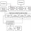
2. General technological scheme for manufacturing the product 7
3. Form process technology, general diagram 9
4. Equipment, materials, software 12
5. Quality control of finished products 13
6. Process map 16
7. Imposition 17
8. Profitability, volume of work and labor intensity 18
Conclusion 19
List of references 21
Abstract
Purpose of the work: Development of technology for manufacturing printing plates for flat offset printing using the “computer – printing plate” scheme.
Legend:
TOII – visual information processing technology.
LTTE – text information processing technology.
LEU – laser exposure device.
Contents of the work: 19 pages, 2 diagrams, 2 drawings.
Introduction
Form processes are a complex of technological operations based on the use of analog and digital technologies for the production of printed forms, which are material carriers of graphic information intended for printing reproduction.
When developing this course project, the following goals were pursued: consolidation and expansion of knowledge within the discipline, acquisition of skills in the process of working with scientific and technical literature and electronic sources of information, development of skills in using reference and regulatory technical documentation on printing equipment and technology, and also on publishing processes, obtaining initial skills in design and calculation of the form process.
Despite the variety of methods for producing printed products, the flat offset printing method occupies a leading position. This is due to the ability to reproduce single- and multi-color images of any complexity with great graphic, gradation and color rendering accuracy using raster structures with a line size of up to 120 lines/cm. This method allows you to print publications on papers of various weights using a wide variety of printing plate manufacturing methods. The method is also characterized by a high degree of automation of the plate and printing processes, good economic indicators, and high-performance printing equipment.
1. Technical characteristics and design indicators of the publication
| Name of indicator and characteristics | Indicator value | |
| in the publication taken as a model | in the edition accepted for development | |
| 1 | 2 | 3 |
| Type of publication: - for the intended purpose - by the symbolic nature of information - by frequency |
training manual text-visual non-periodic |
training manual text-visual non-periodic |
| Publication format: - declared format - product of width and height - share of paper sheet |
80x98 195x255 16 |
80x98 195x255 16 |
| Volume of publication: - in physical printed sheets - in paper sheets - in pages |
19 9,5 304 |
19 9,5 304 |
| Circulation of the publication (thousand copies) | 2500 | 2500 |
| Printing design - colorfulness of the publication and its components - nature of intratext images, rasterization lineature - area of illustrations in stripes and as a percentage of the entire volume - total volume of text in stripes - printing method - type of printing used and type of printing ink |
raster 60 lines/cm 60% 183 121 offset book block: offset cover: coated |
4+4 (book block) 4+0 (cover) raster 60 lines/cm 60% 183 121 offset book block: offset cover: coated ink: for sheetfed offset printing |
| Edition design - number of notebooks - number of pages in one notebook - number and nature of additional elements - method of folding notebooks - method of assembling blocks - cover type and design, design |
19 16 cover 3-fold selection |
19 16 cover 3-fold selection type 3, paper 175 g/m2 coated, 4+0, straight spine |
2. General technological scheme for manufacturing the product
The flat offset printing method uses printing forms on which the printing and space elements are located practically in the same plane. They have selective properties of perceiving oil-containing paint and a moisturizing solution - water or an aqueous solution of weak acids and alcohols. The printing elements of the form are hydrophobic, the whitespace elements are hydrophilic.
Fig.1. Form of flat offset printing: 1 – printing elements, 2 – space elements
The main difference between this printing method and letterpress and intaglio printing is the use of an intermediate surface (offset cylinder) when transferring ink from the printing plate to the printed material.
Flat offset printing forms differ from letterpress and gravure printing forms in two main ways:
- by the absence of a geometric significant difference in height between the printing and white-space elements (CS thickness: 2–4 µm);
- by the presence of a fundamental difference in the physical and chemical properties of the surface of printing and white space elements.
To obtain these forms, it is necessary to create stable hydrophobic printing and hydrophilic space elements on the surface of the form material.
Methods for obtaining printed forms are formatted and element-by-element recording.
Format notation– this is recording an image over the entire area at the same time (photography, copying). Element-by-element notation– the image area is divided into some discrete elements, which are recorded gradually element by element (recording using laser radiation).
Original - a text or graphic work that has undergone editorial and publishing processing and prepared for the production of a printed form. Originals are classified into the following types.
Analog original– an original on a physical medium that requires translation into a digital file for its subsequent processing and reproduction.
Digital original– the original, the informative part of which is contained in encoded form.
Image scanning, computer processing and screen proofing are discussed in detail in the TOII discipline.
Receiving a text file, proofreading and computer layout of pages are studied in the LTTE discipline.
Electronic installation with imposition– placement of pages in the format of a printed sheet of the publication electronically, using a computer publishing system. Installation is controlled visually on the system monitor screen or from a hard copy obtained from the printer.
Electronic version of the printed form– an electronic file containing all the elements that will be located on the printed form, in encoded form. This file will directly record information on the form.
Flat offset printing plate output– production of a flat offset printing plate depending on its characteristics. The layout of the printed product is displayed electronically on plates, skipping the stage of outputting color separated transparencies.
Quality control of the finished printed form– tracking the parameters of the printing form according to the requirements.
3. Form process technology, general diagram
When producing a flat offset printing plate using the “computer – printing plate” scheme, a type of digital technology is used - CTP technology. In turn, it can be divided into two directions, depending on the type of plates: photosensitive and thermosensitive. This technology in both cases uses lasers as a radiation source. That's why this technology is called laser. When using a photosensitive plate, the laser wavelength is 405-410 nm (violet region of the spectrum).
Element-by-element recording of information using this technology is carried out in an autonomous exposure device. CTP technology can be used in both OSU and OBU. This method of producing printed forms involves the use of laser exposure. Various properties of laser exposure are used:
- thermal impact – burning out or thermal decomposition of thin films on blank or printing elements of a future printing form;
- photochemical effect on the photosensitive layer of the form material;
- electrophotographic effect on the photosemiconductor layer.
Page PostScript files control the exposure device, which produces the shape in a similar way to a phototypesetting machine. However, in this case, the software also places pages on the form in accordance with the accepted imposition organization scheme.
In modern printing production, these technologies have not yet taken a leading place. Their implementation is hampered by expensive equipment and uniform materials (imported).
3.1. Structure of a flat offset printing plate for CTP technology
A – plate; B – image recording; B – heating; G – removal of the protective layer; D – printed form after development; 1 – substrate; 2 – photopolymerizable layer; 3 – protective layer; 4 – laser; 5 – heater; 6 – printing element; 6-space element
The technological capabilities of modern offset plates make it possible to use them to produce printing forms suitable for printing almost all types of high-quality products (graphic, advertising, newspaper, magazine, book, etc.).
In plates with a photopolymerizable layer, as a result of the action of radiation, a spatial structure is formed. To enhance the effect of radiation, the exposed plate is heated, which strengthens the polymer structure. For some types of plates with FPS, an additional layer may be located on the surface of this layer to increase the efficiency of the primary effect of laser radiation; in this case, heating after exposure is not carried out. Subsequently, development is carried out, as a result of which the unexposed areas of the layer are removed. After recording an image with a laser source, the exposed plate is usually subjected to the necessary processing in chemical solutions. The process of manufacturing printing plates may include operations such as gumming and technical proofreading, if they are provided for by the technology. Mold control is the final stage of the process.
Requirements for plates:
- roughness – the adhesion of the copy layer to the substrate and, accordingly, its resistance to mechanical stress depend on it;
- circulation resistance – 100-400 thousand prints;
- color contrast after processing the copy allows you to visually assess the quality of the resulting form;
- photosensitivity (S) determines the exposure time of the plate. The higher the photosensitivity, the less time you need to spend on exposure;
- resolution determines the percentage of the reproducible raster dot and the minimum possible stroke width;
- energy sensitivity - the amount of energy per unit surface required for processes to occur in the receiving layers of the plate;
- spectral sensitivity – sensitivity of receiving layers to UV in the visible wavelength range.
4. Equipment, materials, software
To process the text and visual parts of the future edition, you will need such technical means as: a computer, an LCD monitor, a mouse, a keyboard, an inkjet printer, a CTP device, a color proofing device, and a light-proofing device.
Software: Windows Vista Home Premium (operating system), working formats (PS, PDF, EPS, TIFF, JPEG), applications (Microsoft, Adobe, QuarkXpress, CorelDrow, Preps)
Preparation of originals consists of checking them for the presence of all necessary elements and converting them into a single format.
Plate care products
CtP Deletion Pen - correction pencils for thermal plates for CtP produced by AGFA, Kodak, Lastra and some others. Their purpose is to correct forms, remove unnecessary printed elements identified at the stage of operational control. The pencils have a convenient plastic body, are available in two sizes - for coarse and fine correction, and differ in the diameter of the rod.
Positive Deletion Pens are correction pencils whose purpose is to remove printed elements from traditional positive offset plates, where the copy layer is a diazo compound. Pencils are produced in 4 standard sizes, differing in the diameter of the core.
Adding Pen - pencils for adding printed elements to offset plates. They have an aluminum body, two sizes in thickness. Adding printed elements is possible on any type of plate - positive, negative, for exposure in a CtP or copy frame.
Laser exposure device
LEUs for recording information on offset plates are designed to expose radiation from the receiving layer of the plate.
Classification of LEU:
1. Type of plates - for recording on photosensitive plates.
2. Type of laser source – solid-state laser.
3. The design of the device is an internal drum. The forming material is located on the inner surface of a stationary drum, which has the shape of an unfinished cylinder. The image scanning in such a device is carried out vertically due to the continuous rotation of deflectors with one reflective edge and horizontally due to the movement of the deflector and the optical system along the axis of the drum.
4. Purpose – universal.
5. Degree of automation – automated.
6. Format – large.
5. Quality control of finished products
The printed form produced must have the following characteristics:
- coating with a protective colloid;
- absence of surface damage;
- presence of control marks for alignment;
- presence of marks for cutting and folding;
- there should be scales on the edges of the form that allow you to quickly control the printing process;
- the image size must be equal to the specified reproduction size. Permissible deviations: for image sizes up to 40x50 cm - 1 mm;
- the image on the form must be positioned in strict accordance with the layout. The dimensions of the image must correspond to the dimensions of the slide.
- the forms of one set for printing multicolor products must be of the same thickness. Permissible deviations for plates with a thickness of 0.35–0.5 mm are no more than ±0.06 mm; thickness 0.6–0.8 mm no more than ±0.1 mm.
- all printing elements must be reproduced on the form.
- the image on the form must be located strictly in the center, taking into account how the form is secured in the printing machine.
- the form must contain cross marks for alignment, necessary to control the printing process, and marks for folding, trimming and die-cutting (depending on the type of product).
Digital technologies for recording information on plates require quality control:
- testing and calibration of recording devices;
- control of the recording process itself;
- evaluation of printed form performance.
Each stage of control is important, and the first two stages are considered fundamental, since setting up the EI and setting the required powers of the laser source inevitably affects the entire subsequent technological process, and ultimately the quality of the molds. The means for quality control of forms are control test objects. They are presented in digital form and contain a number of fragments of various purposes for visual and instrumental control:
- an information fragment with constant information about the test object itself and variable information with current data about specific recording modes;
- fragments containing pixel graphics objects for visual control of the reproduction of image elements;
- fragments that allow you to evaluate the technological capabilities of the recording device and raster processor, as well as the reproduction and graphic indicators of printed forms.
UGRA/FOGRA DIGITAL PLATE CONTROL
Functional groups:
1. Information part. Contains constant (username) and variable information. The rotation angle of the raster structure, etc. is indicated here.
2. Estimation of resolution. Consists of line elements diverging from the center at different angles.
3. Geometry diagnostics. To evaluate the reproduction of line elements of various sizes.
4. “Chess” zone. Control of reproduction of image elements.
5. Visual assessment area. Visual exposure control.
6. Halftone wedge. Raster scale to control the reproduction of tonal gradation.
DIGI CONTROL WEDGE
Functional groups:
1. Focus. For visual control of laser beam focusing. Consists of 180 radial lines 1 pixel wide.
2. Exposition. Visual exposure control. Contains 6 fields in the shape of circles with checkerboard fillings.
3. Reproduction of line elements. Visual control.
4. Gradation interval.
5. Rasterization. Screening information.
6. Information fragment. Contains permanent information.
The printing plate is considered acceptable if all functional groups provide satisfactory results.
6. Technological process map
| № | Operation name | Purpose of the operation and its essence | Equipment used | Materials used |
| 1 | Recording an image | Formation of a spatial structure in the photosensitive layer | Laser source, EUOD | Form plate with FPS, digital data |
| 2 | Heating | Enhancing the structuring effect | IR drying | Form plate with recorded image |
| 3 | Removing the protective layer | Release of printed elements | Rinse bath | Form plate |
| 4 | Manifestation | Washing out the whitespace layer | CPU | FP, fixative, developer |
| 5 | Additional chemical treatment |
7. Imposition
8. Profitability, volume of work and labor intensity
CTP technology enables the transition to a complete digital process. This means that all stages of production can be controlled and automated: from obtaining images from digital media to finished printed plates. When using this technology, the production process is reduced by several stages. Two developing processes, measuring equipment for film control, copying equipment, perforation and form registration systems, and mounting equipment become unnecessary. Significantly smaller equipment space is required. Productivity increases by 70%. The machine adjustment period is noticeably reduced.
Exposure or recording time is a major factor affecting performance.
Conclusion
While writing the course work, knowledge was gained about CTP technology, photosensitive and heat-sensitive plates. The characteristics of this process were also analyzed and a comparative analysis was carried out. Based on this, we can conclude that the “computer – printing press” system, both in pre-press and in the process of preparing the printing press, makes it possible to achieve greater productivity with high cost savings. The short production time of printing plates, the accuracy of their installation and the automatic pre-adjustment of ink zones based on digital data are a huge advantage.
etc.............