Define lines as the result of the intersection of planes. The intersection of two planes. Intersection of planes of triangles
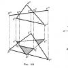
The straight line obtained by the mutual intersection of two planes is completely determined by two points, each of which belongs to both planes. Thus, the straight line K 1 K 2 (Fig. 163), along which the plane defined by the triangle ABC and pl. β, given by the lines DE and DF, passes through the points K 1 and K 2; but at these points the lines AB and AC of the first plane intersect the square. β i.e. points K 1 and K 2 belong to both planes.
Hence, in the general case, to construct the line of intersection of two planes, it is necessary to find any two points, each of which belongs to both planes; these points define the line of intersection of the planes.
To find each of these two points, it is usually necessary to perform special constructions. But if at least one of the intersecting planes is perpendicular to the projection plane, then the construction of projections of the intersection line is simplified. Let's start with this case.
In Fig. 164 shows the intersection of two planes, one of which (defined by the triangle DEF) is located perpendicular to the square. π 2. Since the triangle DEF is projected onto the square π 2 in the form of a straight line (D "F"), the frontal projection of the straight line segment along which both triangles intersect is a segment K " 1 K " 2 on the projection D "F". Further construction is clear from the drawing.

Another example is given in Fig. 165. The horizontally projecting plane α intersects the plane of triangle ABC. The horizontal projection of the line of intersection of these planes - the segment M"N" - is determined on the trace α".
Now let's consider general case of constructing the line of intersection of two planes. Let one of the planes, β, be defined by two intersecting lines, and the other, γ, by two parallel lines. The construction is shown in Fig. 166. As a result of the mutual intersection of the planes β and γ, the straight line K 1 K 2 is obtained. Let's express this by writing: β × γ = K 1 K 2.
To determine the position of points K 1 and K 2, we take two auxiliary frontally projecting planes (α 1 and α 2) intersecting each of the planes β and γ. When planes β and γ intersect with plane α 1. we obtain straight lines with projections 1"2", 1"2" and 3"4", 3"4". These straight lines, located in the square. α 1 , at their intersection determine the first point, K 1 , the line of intersection of the planes β and γ.
Having obtained the projections K" 1 and K" 2, we find on the traces both α" 1 and α" 2 the projections K" 1 and K" 2. This determines the projections K" 1 K" 2 and K" 1 K" 2 of the desired straight line of intersection of the planes β and γ (the projections are drawn by a dash-dot line).
When constructing, you can keep in mind the following: since the auxiliary cutting planes α 1 and α 2 are mutually parallel, then, having constructed projections 1"2" and 3"4", one should take one point each for projections 5"6" and 7"8" , at least 5 and 8, since 5"6"||1"2" and 7"8"||3"4".
In the construction considered, two frontal-projecting planes were taken as auxiliary. Of course, it was possible to take other planes, for example, two horizontal or one horizontal, the other frontal, etc. The essence of the constructions does not change from this. However, such a case may occur. Let us assume that two horizontal planes were taken as auxiliary and those obtained when they intersected

the horizontal planes β and γ turned out to be mutually parallel. But rice. 167 shows that β and γ intersect each other, although their horizontal lines are parallel. Consequently, having received mutually parallel horizontal projections of the horizontals AB and CD and knowing that the planes are not necessarily parallel, but can intersect (along a common horizontal for them), it is necessary to test the planes β and γ using at least a horizontally projecting plane (see . fig. 167); if the straight lines along which this auxiliary plane σ intersects β and γ would also turn out to be parallel to one another, then the planes β and γ do not intersect, but are parallel to one another. In Fig. 167 these lines intersect at point K, through which the line of intersection of planes β and γ passes parallel to straight lines BA and CD.
If the planes are defined by their traces on the projection planes, then it is natural to look for the points that define the line of intersection of the planes at the points of intersection of the same traces of the planes (Fig. 168): the straight line passing through these points is common to both planes, i.e., their line intersections.
The scheme for constructing the line of intersection of two planes (see Fig. 166) can, of course, be extended to the case of specifying planes by their traces. Here the role of auxiliary cutting planes is played by the projection planes themselves:
α × π 1 =h" 0α ; β× π 1 =h" 0β ; h" 0α × h" 0β =M;
α × π 2 =f" 0α ; β× π 2 =f" 0β ; f" 0α × f" 0β =N.
The intersection points of plane traces of the same name are traces of the line of intersection of these planes. Therefore, to construct projections of the line of intersection of planes α and β (Fig. 168), it is necessary: 1) find point M" at the intersection of traces h" 0α and h" 0β

and point N" at the intersection of f" 0α and f" 0β, and along them - projections M" and N"; 2) draw straight lines M"N" and M"N",
In Fig. 169-171 show cases where the direction of the intersection line is known. Therefore, it is enough to have only one point from the intersection of the traces and then draw a straight line through this point, based on the position of the planes and their traces.
Questions for §§ 22-24
- What relative position can the two planes occupy?
- What is the sign of parallelism of two planes?
- How are the frontal traces of two parallel frontally projecting planes mutually located?
- How are the horizontal traces of two parallel horizontally projecting planes mutually located?
- How are the tracks of the same name of two planes parallel to each other mutually located?
- Is the intersection of at least one pair of their tracks of the same name a sign of the mutual intersection of two planes?
- How to establish the relative position of a straight line and a Plane?
- How is the point of intersection of a straight line with a plane perpendicular to one or two projection planes constructed?
- Which point from among those located on a common perpendicular to a) pl. π 1 b) pl. π 2 is considered visible respectively on π 1, on π 2?
- How to construct the line of intersection of two planes, at least one of which is perpendicular to the square. π 1 or to pl. π 2?
- What is the general method for constructing the line of intersection of two planes?
Figure 1.3.25 – Intersection of two planes in general position
An example of constructing a line of intersection of two planes using the method of cutting intermediary planes is presented in Figure 1.3.25. Plane S determined by intersecting lines A And b, and the plane Q– parallel lines With And d.
To find the line l plane intersections S And Q Let's draw two frontally projecting planes W(W 2) And W¢(W¢ 2), who are intermediaries. Plane W intersects these planes S And Q in straight lines 1-2 (1 2 -2 2 , 1 1 -2 1 ) And 3-4 (3 2 -4 2 , 3 1 -4 1 ). Let us denote the point of intersection of these lines by TO(K 1, K 2). Dot TO belongs to three planes simultaneously S, Q, W. Therefore, the point TO S And Q. Plane W¢ intersects planes S And Q in straight lines 5-6 (5 1 -6 1 , 5 2 -6 2 ) And 7-8 (7 1 -8 1 , 7 2 -8 2 ). The point of intersection of these lines is the point K¢. She's like a period TO belongs to the line of intersection of planes S And Q. Therefore, straight l, passing through the points TO And K¢, there is the desired straight line of intersection of these planes S And Q.
 |
Figure 1.3.26 – Intersection of two planes in general position
Figure 1.3.26 shows an example of constructing a line of intersection of two planes by intersecting a straight line with a plane. Planes are defined by triangles ABC And EGF. Auxiliary cutting planes S(S 2) And S¢(S 2) are drawn through the sides E.G. And Sun triangles. Plane S(S 2) intersects the triangle ABC in a straight line 1-2 . Dot TO E.G. And 1-2 . Plane S¢(S¢ 2) intersects the triangle EGF in a straight line 3-4 . Dot K¢ is the result of the intersection of lines Sun And 3-4 . Points TO And K¢ limit the segment of the desired intersection line located within both triangles.
Relative visibility of triangles determined on frontal view using competing points 2 And 4 , of which point 4 sides E.G. covers the point 2 sides Sun. Visibility on the horizontal plane of projections is determined using competing points 5 And 6 , of which point 6 sides E.G. covers the point 5 sides AC.
Curved lines
A curved line can be seen as the trace of a moving point. This point can be a single point or a point belonging to a line or surface moving in space.
Curved lines can be formed by the intersection of a curved surface with a plane (in the general case), by the mutual intersection of two surfaces, at least one of which is a curve.
The law of formation of a curved line is the set of conditions that determine this line. A point, line, surface moves in space, subject to different conditions. A plane can intersect a variety of curved surfaces in a variety of directions. A wide variety of surfaces can intersect each other at different positions relative to each other. It follows that the formation of a curved line can be subject to an infinite number of conditions and an infinite number of curved lines can be formed. In addition, the same curved line can be formed in different ways.
For example, an ellipse can be formed by the movement of a point in a plane, in which at any given moment the sum of the distances from this point to two other fixed points - the foci of the ellipse - is constant and equal to the major axis of the ellipse. But an ellipse can also be formed by the intersection of a circular cylinder with a plane located arbitrarily with respect to its axis or by the complete intersection of the surfaces of two circular cylinders of the same diameter.
All curved lines according to the position of their points in space are divided into two types: flat curves– curves, all points of which lie in the same plane (for example, circle, ellipse, parabola, etc.) and spatial curves– curves whose points do not lie in the same plane, for example, a helix
A straight line in space can be defined as the line of intersection of two non-parallel planes and, that is, as a set of points satisfying a system of two linear equations
 (V.5)
(V.5)
The converse statement is also true: a system of two independent linear equations of the form (V.5) defines a straight line as the line of intersection of planes (if they are not parallel). The equations of system (V.5) are called general equation straight line in space  .
.
ExampleV.12 . Compose a canonical equation of a straight line given by the general equations of planes

Solution. To write the canonical equation of a line or, which is the same thing, the equation of a line passing through two given points, you need to find the coordinates of any two points on the line. They can be the points of intersection of a straight line with any two coordinate planes, for example Oyz And Oxz.
Point of intersection of a line and a plane Oyz has an abscissa  . Therefore, assuming in this system of equations
  , we get a system with two variables:

Her decision  ,
, along with
  defines a point
  the desired straight line. Assuming in this system of equations
  , we get the system

whose solution  ,
, along with
  defines a point
  intersection of a line with a plane Oxz.
Now let's write down the equations of the line passing through the points  And
And  :
: or
or  , Where
  will be the direction vector of this straight line.
ExampleV.13.
The straight line is given by the canonical equation  . Write a general equation for this line.
Solution. The canonical equation of a line can be written as a system of two independent equations:


We have obtained the general equation of a straight line, which is now given by the intersection of two planes, one of which  parallel to the axis Oz
(
parallel to the axis Oz
( ), and the other
  – axes Oh
(
– axes Oh
( ).
).
This straight line can be represented as a line of intersection of two other planes by writing its canonical equation in the form of another pair of independent equations:


Comment . The same straight line can be defined by different systems of two linear equations (that is, by the intersection of different planes, since an infinite number of planes can be drawn through one straight line), as well as by different canonical equations (depending on the choice of a point on the straight line and its direction vector) .
A non-zero vector parallel to a straight line, we will call it guide vector .
Let in three-dimensional space  a straight line is given l, passing through the point
  , and its direction vector
  .
.
Any vector  , Where
  , lying on a line, is collinear with the vector
  , therefore their coordinates are proportional, that is
 . (V.6)
This equation is called the canonical equation of the line. In the special case when ﻉ is a plane, we obtain the equation of a straight line on the plane
 . (V.7)
ExampleV.14.
Find the equation of a line passing through two points  ,
, .
.
 ,
,
Where  ,
, ,
, .
.
It is convenient to write equation (V.6) in parametric form. Since the coordinates of the direction vectors of parallel lines are proportional, then, assuming
 ,
,

Where t
- parameter,  .
.
Distance from point to line
Consider a two-dimensional Euclidean space ﻉ with a Cartesian coordinate system. Let the point  ﻉ and lﻉ. Let's find the distance from this point to the line. Let's put
  , and straight l given by the equation
  (Fig.V.8).
Distance  , vector
  , Where
  – normal line vector l,
 And
And  – collinear, so their coordinates are proportional, that is
  , hence,
  ,
,
 .
.

From here  or multiplying these equations by A And B respectively, and adding them, we find
  , from here
 .
.
 (V.8)
(V.8)
determines the distance from a point  to a straight line
  .
.
ExampleV.15.
Find the equation of a line passing through a point  perpendicular to a straight line l:
 and find the distance from
  to a straight line l.
From Fig. V.8 we have  , and the normal vector is straight l
 . From the perpendicularity condition we have
Because  , That
 . (V.9)
This is the equation of a line passing through a point  ,perpendicular to a straight line
  .
.
Let us have the equation of the line (V.9) passing through the point  , perpendicular to the line l:
 . Find the distance from the point
  to a straight line l, using formula (V.8).
To find the required distance, it is enough to find the equation of a straight line passing through two points  and period
  lying on the line at the base of the perpendicular. Let
  , Then
Because  , and the vector
  , That
 . (V.11)
Since the point  lies on a straight line l, then we have another equality
  or
or

Let us reduce the system to a form convenient for applying the Cramer method

Its solution has the form
 ,
,
 . (V.12)
Substituting (V.12) into (V.10), we obtain the original distance.
ExampleV.16.
A point is given in two-dimensional space  and straight
  . Find the distance from a point
  to a straight line; write down the equation of a line passing through a point
  perpendicular to a given line and find the distance from the point
  to the base of the perpendicular to the original line.
By formula (V.8) we have
We find the equation of a line containing a perpendicular as a line passing through two points  And
And  , using formula (V.11). Because
  , then, taking into account the fact that
  , A
, A  , we have
 .
.
To find coordinates  we have a system taking into account the fact that the point
  lies on the original line

Hence,  ,
, , from here.
Consider the three-dimensional Euclidean space ﻉ. Let the point  ﻉ and plane ﻉ. Let's find the distance from this point
  to the plane given by the equation (Fig. V.9).

Analogously to two-dimensional space we have  and vector
  , ah, from here
 . (V.13)
We write the equation of a line containing a perpendicular to the plane as the equation of a line passing through two points  And
And  , lying in the plane:
 . (V.14)
To find the coordinates of a point  to any two equalities of formula (V.14) we add the equation
Solving the system of three equations (V.14), (V.15), we find  ,
, ,
, – point coordinates
  . Then the equation of the perpendicular will be written in the form
 .
.
To find the distance from a point  to the plane instead of formula (V.13) we use
The straight line of intersection of two planes is determined by two points, each of which belongs to both planes, or one point belonging to two planes, and the known direction of the line. In both cases, the task is to find a point common to the two planes.
The general technique for constructing the line of intersection of two planes is as follows. An auxiliary plane is introduced, lines of intersection of the auxiliary plane with two given ones are constructed, and the common point of the two planes is found at the intersection of the constructed lines. To find the second common point, the construction is repeated using another auxiliary plane.
Figure 5 shows a visual representation of the intersection line K 1 K 2 two planes R And Q.
Figure 5
For a visual representation of the construction of the first common point of the line of intersection of planes R And Q(Figure 6) an auxiliary plane has been introduced S. With plane R it intersects along the line 1-2 , with a plane Q– along the line 3-4 . At the intersection of lines 1-2 And 3-4 first common point determined K 1 two planes R And Q– the first point of the line of their intersection.
Similarly, a new cutting plane is introduced and the second point of the intersection line is constructed.
Figure 6
A special case of constructing the line of intersection of two planes when one of them is projecting. In this case, the construction of the intersection line is simplified by the fact that one of its projections coincides with the projection of the projecting plane onto the projection plane to which it is perpendicular.
As an example, Figure 7 shows the construction of projections m"n", mn intersection lines MN frontal projection plane R with a triangle plane ABC.
Figure 7
On the frontal projection at the intersection of projections a"b" And a"c" with a trace P u find frontal projections m" And n" two common points of given planes. Horizontal projections were constructed based on them m And n on horizontal projections ab And ac sides of the triangle. Through dots m And n We draw a horizontal projection of the line of intersection of the planes. When looking along the arrow S from the frontal projection it is obvious that part of the triangle is to the left of the intersection line MN(m"n") is above the plane R, i.e. visible, the rest is under the plane R, i.e. invisible (section mbcn shown with a dashed line).
Another example of constructing the line of intersection of two triangular plates ABC And DEF, one of which ( DEF) is specified as a horizontally projecting plane, shown in Figure 8.
Figure 8
On a horizontal projection at the intersection of horizontal projections ab And bc parties DABC with projection dfe of the second triangle we find horizontal projections m And n points of their intersection. According to them on the frontal projections of the sides a"b" And b"c" constructing frontal projections m" And n" intersection points MN. On the frontal projection we note the visibility of parts of the triangles, guided by the following: when looking along the arrow S from the horizontal projection it is obvious that the side AC is in front of the plane of the triangle DEF.
Therefore, the side AC and the part of the triangle limited by it ABC to the intersection line MN visible (i.e. the frontal projection of the quadrilateral is visible a"c"n"m"). Visible part of the frontal projection DDEF shaded in the drawing.
Construction of the line of intersection of planes in general position. Figure 9 shows the construction of projections m"n", mn lines of intersection of two planes, one of which is defined by projections a"b", b"c", ab, bc two intersecting lines, the other - projections d"e", f"g", de, fg two parallel lines.
Two horizontal planes, defined by the traces, are taken as auxiliary planes R u And T u .
Plane R intersects the first given plane in a straight line 1-2 , the second - in a straight line 3-4 . According to frontal projections 1", 2" And 3", 4" we find horizontal projections using communication lines 1, 2 And 3, 4 on horizontal projections ab, bc, de, fg straight Through them we draw horizontal projections of lines 1-2 And 3-4 intersection lines. Mark a point m– horizontal projection of a common point M three planes - two given and auxiliary R. Using it we determine the frontal projection m" on the frontal track R u auxiliary plane.
Figure 9
Auxiliary planes T And R parallel. The lines of their intersection with given planes are also parallel. Therefore, horizontal projections of the lines of intersection of the plane T with given planes are drawn through the projection b parallel to the projection 1-2 and through projection 5 parallel to the projection 3-4 . A horizontal projection was found at their intersection n the second common point of the three planes, i.e. lines of intersection of two given planes. Along it on the frontal trail T u frontal projection is constructed on the auxiliary plane n". Through the constructed projections m",n" And m, n We carry out frontal and horizontal projections of the desired intersection line MN.
Two planes intersect each other in a straight line. To construct it, it is necessary to determine two points that simultaneously belong to each of the given planes. Let's look at how this is done using the following examples.
Let us find the line of intersection of generic planes α and β for the case when pl. α is given by the projections of triangle ABC, and pl. β – parallel lines d and e. The solution to this problem is carried out by constructing points L 1 and L 2 belonging to the intersection line.
Solution
- We introduce an auxiliary horizontal plane γ 1. It intersects α and β along straight lines. The frontal projections of these straight lines, 1""C"" and 2""3"", coincide with the frontal trace of the square. γ 1. It is designated in the figure as f 0 γ 1 and is located parallel to the x axis.
- We determine horizontal projections 1"C" and 2"3" along the communication lines.
- We find the horizontal projection of point L 1 at the intersection of lines 1"C" and 2"3". The frontal projection of point L 1 lies on the frontal trace of the plane γ.
- We introduce an auxiliary horizontal plane γ 2. Using constructions similar to those described in paragraphs 1, 2, 3, we find the projections of point L 2.
- Through L 1 and L 2 we draw the desired straight line l.
It is worth noting that as a pl. γ it is convenient to use both level planes and projection planes.
Let us find the line of intersection of the planes α and β, defined by the traces. This task is much simpler than the previous one. It does not require the introduction of auxiliary planes. Their role is played by the projection planes P 1 and P 2.

Construction algorithm
- We find point L" 1, located at the intersection of the horizontal traces h 0 α and h 0 β. Point L"" 1 lies on the x-axis. Its position is determined using a connection line drawn from L" 1.
- We find point L"" 2 at the intersection of the frontal traces pl. α and β. Point L" 2 lies on the x axis. Its position is determined along the connection line drawn from L"" 2.
- We draw straight lines l" and l"" through the corresponding projections of points L 1 and L 2, as shown in the figure.
Thus, the straight line l passing through the intersection points of the traces of the planes is the desired one.
Intersection of planes of triangles
Let's consider constructing the line of intersection of the planes defined by triangles ABC and DEF, and determining their visibility using the competing points method.

Construction algorithm
- Through the straight line DE we draw the frontally projecting plane σ: its trace f 0σ is indicated in the drawing. The plane σ intersects the triangle ABC along straight line 35. Having marked the points 3""=A""B""∩f 0σ and 5""=A""С""∩f 0σ, we determine the position (∙)3" and (∙) 5" along communication lines at ΔA"B"C".
- We find the horizontal projection N"=D"E"∩3"5" of the point N of the intersection of straight lines DE and 35, which lie in the auxiliary plane σ. The projection N"" is located on the frontal trace f 0σ on the same connection line with N".
- Through N and K we draw the desired straight line NK - the line of intersection of ΔABC and ΔDEF.
Through straight line BC we draw the frontally projecting plane τ: its trace f 0τ is indicated in the drawing. Using constructions similar to those described in paragraphs 1 and 2 of the algorithm, we find the projections of point K.
Visibility Definition
Frontally competing points 4 and 5, belonging to ΔDEF and ΔABC, respectively, are located on the same frontally projecting straight line, but are located at different distances from the projection plane π 2 . Since (∙)5" is closer to the observer than (∙)4", the compartment ΔABC with its (∙)5 is visible in the projection onto the square. π 2. On the opposite side of the N""K"" line, the visibility of the triangles changes.
Horizontally competing points 6 and 7, belonging to ΔABC and ΔDEF, respectively, are on the same horizontally projecting straight line, but located at different distances from the projection plane π 1 . Since (∙)6"" is located higher than (∙)7"", then compartment ΔABC with its (∙)6 is visible in the projection onto the square. π 1. On the opposite side of the N"K" line, the visibility of the triangles changes.
Read also...
- What are the reasons for the successful military campaigns of the Mongols?
- Intersection of two planes
- Why do you dream of white doves: for the fulfillment of desires, meeting true love Seeing white doves in a dream
- I dreamed of a white dove - interpretation of the dream according to the dream book. What does it mean when you dream of a white dove