Adjustment of the underfloor heating collector with flow meters. Adjustment of temperature of a water heat-insulated floor. #water heated floor, #mixing unit, #adjustment of underfloor heating, #electric boiler heating
After carrying out all the work on laying the contours of the water-heated floor, the crucial moment comes to connect them to the collector.
In this article, we will consider a step-by-step sequence of how to do it correctly, when and what tests should be carried out, and what mistakes you may encounter in this matter. We will also touch upon the issue of automatic temperature control in the premises.
Connecting floor heating pipes to the comb
Installation of heating pipes begins with connecting the free end of the pipe to the fitting of the distribution manifold supply manifold.
For most modern manufacturers, such as Rehau, this is done using a Eurocone threaded connection. It is considered one of the simplest and most reliable in execution today. 
The Eurocone often goes under 17mm in diameter, while a lot of users assemble their underfloor heating system from the 16th pipe. In this case, you will have to calibrate the tube to the specified size. 
You can use the original cross-linked polyethylene tubes from Rehau, which come in the 17th diameter, then everything should go in without additional gestures.

Someone expands the wall with metal shears. Everything seems to fit, but you will not achieve a perfectly even contact in this way. 
The reliability of the connection from this will eventually lose. With frequent temperature changes, a leak is quite possible in this place in the future.


Then by hand tighten the end of the tube to the connecting fitting. 
In order not to break the fitting on the manifold, the final tightening should be done using two wrenches. With one you fix the hexagon on the fitting, and with the second you tighten the threaded connection. 
When installing elastic pipes, it is better to enclose the collector connection near the floor in a rotation lock. 
At the entrance to the screed, it is necessary to put on a protective casing made of corrugated pipe or thermal insulation on the pipes. The recommended length is at least 0.5m.
25cm will go out, and the other 25cm will be located in the screed itself. 
Mistake No. 2 - if you do not put on a protective cover, the tube will be damaged by the sharp edges of the screed during its thermal elongation.
Heating circuits should be laid in 100 mm increments. 
The installation of the circuit ends by bringing the other end of the pipe to the corresponding fitting of the return manifold. 
In the area where the pipes are connected to the collector, where the distance between the pipes is minimal or they go close to each other, they must also be placed in thermal insulation or corrugation.
This will prevent overheating of the screed and reduce the surface temperature near the collector itself. In exactly the same way, alternately connect all the other circuits. 
Mistake number 3 - do not confuse the supply with the return. Not always where the flow meters are located, supply hoses are connected, and return hoses are connected to another comb.
It all depends on the type of rotameter. So check out the documentation. In one case, the stem must be deflected downward by the flow of water, so the flow is started through it. 
And in the other, on the contrary, raise the stem up. 
You can tell them apart by the scale. For those that serve, zero will be at the very top, and the scale will accordingly increase towards the bottom. 
Those on the return line have zero from the bottom, and the numbers increase upwards.
Filling with water and pressure testing
Once connected, it's time to fill the system with water.
This should be done not through the heating boiler, but directly through the taps for descent and filling. They are located on the rear plug of the distribution manifold. 
Mistake number 4 - if you pump water through the boiler, there is a risk of failure of the circulation pump.
Be sure to cover Ball Valves with boiler feed. 
Next, using a special key, close all the circuits except one. It is from him that you will begin filling the system with water. 
Also close all taps on the rotameters, except for one. 
Now you can connect the water hose to the drain cock on the supply manifold.
A hose is connected to the return comb to drain the water. After that, you can slowly start the water. 
Lower the drain hose from the return comb into the sewer or just into a bucket and wait until all the air has drained.
As soon as one water flows, the valve of this circuit can be closed and proceed to the next one. The whole procedure is repeated again.
After filling all the circuits, you can start supplying water to the distribution system through the heating unit or the boiler itself.
Only after that, open the ball valves on the manifold and finally release the remaining air through the air vents. 
Before pouring the screed, the underfloor heating pipelines themselves should be checked for tightness.
Tests are made on cold water. In this case, the test pressure must exceed the working pressure by 1.5 times. 
As a rule, hydraulic tests are carried out within 3 hours. During the first hour, every 10 minutes, the decreasing pressure is adjusted to the desired one. 
And during the next 2 hours, a control measurement is made.
The pressure in a working and serviceable system should not decrease from the original one by more than 2 bar.
Mistake No. 5 - trust only the pressure readings, without visual and physical (by hand) checking of the joints.
You definitely need to make sure that not only the tubes, but also all joints and connections are tight. The fact is that a small digging, pressure drop is not determined in any way.
As a result, you are satisfied with all the indications and finally fill the screed and mount the entire system. And after a while, these wet places will show themselves in all their glory. 
As an exception, if you have a negative temperature at the facility, pneumatic tests with compressed air or inert gas are allowed for floor-standing systems. 
The tightness of each connection is checked with a foaming composition.
Hydraulic tests are usually documented in a protocol.
Balancing the contours and pouring the screed
Further there is a hydraulic balancing of separate contours of a heat-insulated floor. To do this, use a special adjusting key to set the value specified by the designer on the fine adjustment valves. 
If you do not have such valves, then set estimated flow coolant for each heating circuit. This is done by flowmeters.
They set the duct in order to align all the contours with each other. After all, the length of each can be any, and your coolant must evenly pass through all the contours, and not just along the shortest one. 
After pressure testing and leak testing, the pipes are filled with a screed. In this case, the system must be filled with cold water and be under pressure.
Mistake number 6 - pour the screed with empty pipes.
When the screed gains strength, thermal tests are carried out. This takes a period of time equal to 7 days.
At the same time, during the first three days, the heating system is washed with water at a temperature of 20 degrees. In the next 4 days, the maximum operating temperature is set and the heating of all circuits is checked.
Thermal testing is also documented. 
Automatic temperature control of underfloor heating
If the heated floors are branched and heat a large number of rooms, then it is advisable to equip them with automatic control. 
This will save you from constantly tightening the control valves on the manifold.
Installation of the automatic control system begins with the installation of a terminal block on a din-rail in the switch cabinet. 
It is mounted directly above the distribution manifold.
First, connect the mains voltage to this block. 
Then servos are installed on the return manifold of the distribution manifold. 
The page is devoted to such a topic as adjusting a warm water floor: manual and automation of control, how to properly set up and adjust, as well as such a question as the rules for the first run.
Systems of the built-in water heating gain the increasing popularity.
To enjoy their advantages as primary or auxiliary heating, it is necessary to be able to correctly adjust the warm water floor - both during the initial start-up and to control the operation of the system during its operation.
Rules for the first start-up of the system
Setting up a warm water floor begins from the very moment of its first start after installation. This is an important and crucial stage, which largely determines the reliability and durability of the laid "pie". Thus, there is a “setting” not only directly of the elements of the heating system, but also of the floor itself (screed, floor covering), which is in contact with heat from the pipes.
The first start-up of a water-heated floor is carried out before laying a decorative floor covering in order to dry the concrete cake.
- The first start-up of the system is carried out with a dry concrete screed(the usual setting time for cement-concrete mixtures is from 17 to 28 days).
- If time does not endure, the repair is delayed, and the cold has already come, it is allowed to gradually start the system with an increase in the temperature of the coolant by no more than 1⁰С per day. At the same time, at least 2 weeks should pass from pouring the screed to turning on the floor for gradual heating. In this way, it will be possible to dry the finishing screed faster, eliminating the risk of thermal shock, stress and cracking of the cement.
- Extremely it is important to dry the screed well before laying the decorative coating, especially sensitive to moisture (parquet, laminate, etc.).
Preparatory stage
The question of how to properly set up warm water floors in order to ensure high efficiency and reliability of the system is relevant not only at the first start, but also remains urgent every year before the next start of the system.
We are talking about starting air and filling the system with coolant. Even if the heated floors are equipped with state-of-the-art sensors and electronic or radio-controlled programmers, this process is not complete without the direct participation of a person.
This is a kind of starting manual adjustment in warm water floors.
Regardless of whether floor heating is used as an independent or supplementary radiator, before starting the underfloor heating, make sure that all valves and gates on the distribution manifold are closed - both for supply and return.
If the built-in heating is used as an additional one, then by blocking all the loops of the water floor, first you need to fill the main heating system with coolant.
Next, you need to open the supply and return on one loop by turning on circulation pump at minimum speed and allowing the circuit to gradually fill with water without the formation of air pockets. This is the basic rule of how to set up a warm water floor. Air will be vented through the air vent on the manifold.
The boiler can already be started for heating by setting the temperature to 30, maximum 40⁰С. Need to control delivery warm water into an open loop, as well as the return of warm water in the return line. If everything is normal, the tested circuit works well, the supply and return valves on it overlap, and all operations are repeated with the next circuit. And so on until the system is filled and deaerated.
At the next stage, before properly adjusting the warm water floor, it is necessary to open all the valves completely and be patient, especially in the case of manual regulation without the use of modern automation (controllers, regulators and servos). It is worth remembering that water heated floors are an inertial system that does not instantly respond to adjustments made. It is necessary to wait for the system to warm up and evaluate the temperature regime of operation on each circuit.
It is worth remembering that the “response” time of the system to the change made (warming up or cooling by controlling the temperature of heating the coolant in the boiler or controlling the volume of the coolant entering the circuits), depending on the length of the circuits, the laying pattern, the type and diameter of the pipes, the thickness of the screed, may range from a couple of hours to a day.
Adjustment of a warm water floor
Manual
It is not difficult to guess how to regulate a warm water floor manually using a collector.
 All loops of the heated floor are connected to the distribution manifold to the inlet and return. The temperature of the coolant entering the collector and, accordingly, the coolant loops will be the same.
And here at the outlet of each of the loops, the water temperature may vary. It depends on the length of the loop and other factors.
Depending on the required temperature and in order to achieve the desired comfort of heating the room and heat transfer, adjustment of the comb of the water-heated floor is carried out. So you can change the amount of water entering the loop and, accordingly, the intensity of its heat transfer, and as a result, the heating temperature of the floor covering.
Manual control of the temperature regime of the warm floor can be carried out in two ways:
- By manipulating control valves. In this case, you have to focus only on your own feelings. When the weather outside the window is changeable, the valves have to be turned often.
- Adjustment of a warm water floor by flowmeters. This method also involves the manipulation of cranes, however, it greatly facilitates the configuration of the system. Flowmeters are installed on the manifold at the inlet to each loop. Wherein allowable difference in the readings between the flow meters is from 0.3 to 0.5 liters.

Temperature control automation
Since it is inconvenient to control and adjust the heating system manually, the question arises of how to adjust the warm water floor by automating the process.
For this purpose, devices such as:
- thermostats and thermostats, which control the temperature taking into account the readings from the floor or air temperature sensors in the room, being control devices;
- servo drives, which are actuators for reducing or increasing the amount of coolant entering the loop.
The thermostat is installed, as a rule, one per room, it can be single or multi-zone. Servo drives (servomotors) are installed at the supply of each circuit.
Thermostats (thermoregulators) can be mechanical and electronic. The first type is the most inexpensive and reliable. Assumes manual setting of the required temperature range. The electronic regulator of a water heated floor allows you to control several parameters at once and even program the heating system (depending on the capabilities of the model, as well as the requirements for temperature in a particular area, by time of day, etc.). These are more expensive devices.

Conclusion
Regulation of the mode of operation of a warm water floor is a mandatory process that ensures efficiency, reliability and economy of heating, and comfortable conditions for a person.
One of the important nodes that ensure the reliable functioning of a warm water floor is a collector. Among the diverse range, judging by the advice of experts and consumer reviews, Valtec models are popular.
The functionality of the equipment and its features
The main functional role played by the collector in the system of underfloor heating with a liquid heat carrier is the distribution of water flows. Outwardly, it is a pipe with branches equipped with valves.
Manifold block VALTEC
With the help of this device, unnecessary air is excluded from the liquid, if necessary, the system is drained. Another of the important functions of the collector is the implementation of regulation - manual or automatic nominal size of flows that are sent to different water circuits.

The equipment is placed in a special collector cabinet, which is fixed on the wall. In some cases, a utility room is allocated for it.
The device is included in the composition of the collector block, equipped, in addition to it, with a number of other elements:

- control valves;
- flow meters;
- mounting brackets;
- shut-off valves with manual control;
- shut-off valves;
- end caps;
- drainage valves;
- air vents.
The collector pipe can have several outlets (3–12). The type of connection is made according to the Eurocone standard, which has an external thread. There are restrictions on the limiting pressure of 10 bar, correlated with a coolant temperature ≤ 90°C.
Advantages
Like all Valtek products, the collector has a number of positive distinctive characteristics that cause increased interest in them from consumers:

- thanks to the factory assembly, the entire manifold block undergoes multi-level repeated testing for compliance with safety and quality requirements during the production process;
- products supplied to the Russian consumer are fully adapted to the relevant conditions;
- the purchased collector Valtec has all the necessary certificates and a technical passport.
Manufactured from stainless steel manifold High Quality grade AISI 304.
Purpose of flowmeters
In terms of its functionality, the flowmeter (or rotameter), as well as all Valtec products, has high quality characteristics. It provides regulation and visual monitoring of the flow rate of the heat carrier circulating in the water floor heating loops connected to the collector placed in the cabinet.

The presence of such a device facilitates the adjustment of the functioning of the warm floor, especially with multi-circuit wiring. Proper regulation by flow meters of the amount of coolant entering each water circuit ensures uniform heating of the entire surface of the warm floor. To manually adjust the flow meter, the pipe is first measured along the entire length of the circuit, since the set pressure value depends on this indicator.
When studying a unit equipped with Valtec flowmeters, it is necessary to pay attention to the fact that the desired direction of the liquid flow is indicated by an arrow on their body. The scale of the device is calibrated with a range of indicators from 1 to 4 l / min.

A flow meter with a nominal pressure of 10 bar is installed when a water heating circuit is installed on the return manifold outlets. The throughput is 2.75 m3/hour. To perform the connection, the Eurocone standard with a union nut is used.
The Valtec flow meter is made of brass - the body, of polycarbonate with a transparent texture - a tube equipped with a scale. Polypropylene is also used for the float and stainless steel for the spring.
Warm floor Valtec
manifold cabinets
To ensure full compatibility of all underfloor heating units in the Valtec product line, you can choose a manifold cabinet of the right size. It is characterized by increased depth and is designed to be placed inside collectors, pump-mixing modules and other elements of heating systems.
The Valtek cabinet is made of galvanized steel with an anti-corrosion enamel or polymer coating. Perforations are provided on the side walls, which is necessary so that the pipe supplied to the collector passes freely inside. The door has a lock.
Pumping and mixing unit VALTEC
Inside the cabinet has built-in rails that facilitate the installation of equipment on them. A dynamic frame is used to adjust the depth, and retractable legs adjust the height.

Analyzing the advantages of this type of Valtec products, it can be noted that the cabinet has compact dimensions and is easy to assemble. It is environmentally friendly and easy to use. Thanks to a well-thought-out fastening system, all the strapping equipment fits inside. Access to each node is facilitated, and there is no need to install additional protection systems, since it is enough to close the cabinet with a lock.
Installation requirements
During installation, it is advisable to place the Valtek manifold in relation to the heating system in a higher position, which will allow more efficient removal of air from the underfloor heating pipes. It is desirable that the length of the circuits connected to the collector be approximately the same.

Properly mounted in a collector cabinet, the device, when a hot coolant enters it, separates the flows, directing them to a zone valve equipped with a thermostat. After the hot and cooled streams are mixed until the operating temperature is reached, the coolant flows back through the system mixing pump and diverges through the connected water floor circuits.
Setting
You can adjust the Valtec collector manually, and it is also possible to do it automatically if the servo drives are installed on the supply. This operation is necessary for the system to function in the specified mode in the future, as well as for the purpose of diagnosing possible malfunctions.
When setting up, you will need to perform several sequential operations in accordance with the instructions supplied with the product.


It remains to check during the test run the uniformity of heating of the underfloor heating circuits, as well as the difference in the temperature of the coolant at the supply and return, established by the manufacturer. If all tuning instructions are taken into account, the desired heating efficiency and durability of the entire system will be ensured.
Video: Collector for underfloor heating
kaminyn.ru
Collector group for underfloor heating: pump 6 circuits, flow meter
For the average person, the underfloor heating system does not look complicated, just hot water pipes laid inside the screed. In practice, it's not like that at all. Due to the special requirements and mechanics of work, there is always a collector group for a warm floor in the piping system, which distributes the coolant and provides microclimate control in each room.

The problems of the heating system
Underfloor heating is one of the most popular modern systems heating. This is due to the high functionality, efficiency of the pipe structure, as well as the ability to flexibly adjust the temperature in each room. The last problem is solved by a collector for a warm floor. This device eliminates the most important problem of building a heating system.
The operation of the pipe structure located in the floor should occur with a liquid temperature of 35-40 degrees. Such an indicator of heating can be provided by gas or other condensing-type boilers.
In practice, such devices are expensive and difficult to set up, so standard heating systems are used. At the outlet of the heating unit, the water has a temperature of up to 80-90 degrees. Walking on such a surface is not comfortable. Therefore, a floor heating collector is installed in the heating system. It works in the following way:
- water coming from the heating boiler enters the collector block;
- the coolant is mixed with water from the return circuit, its temperature drops;
- the collector group distributes liquid with an acceptable temperature to all heating circuits.
The average solution that can be purchased on the mass market is collectors for underfloor heating with 6 circuits. This is a diagram for an ordinary three-room apartment. Separate circulation routes are made for rooms, kitchens, bathrooms and hallways. Therefore, the collector unit of this type is common and is offered in various modifications.
Why do I need an additional circulation pump
The collector group for underfloor heating is often equipped with its own additional pressure pump. This unit is needed to increase pressure and provide isolated circulation that does not depend on heating equipment. This is especially important if the floor heating collector group uses two-way valves.
A more advanced and technologically advanced solution uses three-way mixing units. But the presence of an additional circulation pump is still recommended. Although the three-way valve does not provide for shutting off the supply, it reduces the amount of coolant pumped by the heating boiler.
An additional circulation pump, which is equipped with a collector group for underfloor heating, solves all pressure problems.

Why flow meters are needed
A brief principle of operation on which the underfloor heating collector in the circulation system is built is discussed above. But after solving the problem of reducing the temperature of the coolant at the inlet of the circuits, another problem arises. Briefly, it can be described as follows:
- water of equal temperature enters each room;
- the length of the pipes laid in the floor in each room is different;
- water of different temperatures enters the collector for underfloor heating after passing through the heating circuits of individual rooms.
Without balancing the flow, a floor heating collector will create a situation where it is very hot in small rooms and cool in large ones. Such warm floors can hardly be called effective. The flow meter for the underfloor heating collector solves the problem of heat balancing as follows:
- equipped with a temperature sensor, determines the characteristics of the liquid coming from the return;
- depending on the results obtained, reduces or completely blocks the flow of hot water;
- mixing of the heated coolant from the supply is stopped until the return temperature drops to the set value.
The flow meter for the underfloor heating collector is easily adjustable. The simplest products allow manual setting systems. In this case, the user himself selects comfortable conditions in a particular room by screwing or loosening the knot head.
Complex products are equipped with an interface for receiving a signal from an external sensor. It is possible to purchase a floor heating collector system complete with a pump that has flow meters designed for use with room temperature controllers.
Solutions are also available that are guided by indicators of the external environment. When the outside temperature drops, the flow meter will automatically increase circulation. It is possible to control the operation of several circuits at once on the signal of one temperature detector.
The flow meter is one of the main details that clearly standardize the installation of the collector assembly. This element design works reliably only in a vertical position. Therefore, when installing the manifold, it will be necessary to carry out work so that the flow meters are located appropriately.
Collector group with flowmeter:
How does a manifold with two-way valves work?
If an underfloor heating manifold assembly with a pump is purchased, two-way valves will be used for an inexpensive solution. They work according to the following scheme:
- the temperature sensor constantly monitors the temperature of the water in the liquid mixing zone;
- as soon as the indicators exceed the set value, the hot water supply is shut off;
- the circulation pump continues to work, pumping the coolant;
- when the water temperature drops, the two-way valve opens slightly and hot water from the boiler is mixed into the heating circuits.
The main feature of the system operating on two-way valves is the periodic shutdown of the hot water supply. Therefore, in order to avoid temperature fluctuations, it is recommended that the heating structure be connected to boilers designed for pumping not a constant, but a variable fluid flow.
The two-way valve has a major drawback. It has low throughput. This does not affect the operation of the system, since the supply of hot water in balanced mode is relatively small. But a low rate of water passage leads to inevitable clogging of the valve. Therefore, it must be installed immediately so that replacement or maintenance can be carried out. Another recommendation for the use of two-way valves: use them for heating areas of less than 200 square meters.
How a 3-way valve system works
Three-way valve considered the best solution for heating large rooms, subject to the existence of several contours. This node works like this:
- there is a partition inside the valve;
- liquids from the return and supply from the boiler are constantly mixed;
- to adjust the temperature, just turn the top valve head.
Simple systems offer manual control of the mixing unit. But the three-way valve provides the possibility of automatic regulation. This is done using a servo drive, which receives signals from temperature sensors. These can be devices that are located in specific rooms or determine the parameters of the climate outside the building.
The disadvantages of a three-way sensor include the possibility of a sharp increase in temperature in the heating circuit. This happens after a slight turn of the head, which complicates the manual adjustment of the microclimate parameters. When using temperature sensors and servomotors, there is also a risk of obtaining incorrect data. But it is relatively small. The 3-way valve has good capacity, is reliable and rarely clogs.
If it is decided to make a collector for a warm floor with your own hands, it is imperative to provide an air release valve. Other design and adjustment elements may be as follows:
- flowmeters that will require elbows of a particular format with threaded connections, can be replaced shutoff valves. A simple faucet that regulates the flow is quite effective;
- to set a constant mode of heat input, it is recommended to use a three-way valve. Its setting will be fine enough, but after its completion, the system will not require intervention for a long time.
When placing a self-made collector in a wall cabinet or other places with limited space, sufficient space should be provided for the circulation pump. In addition, it will be necessary to provide a power supply and convenient access to adjustment points.
To improve the performance of a self-made manifold, you can use a three-way valve with a thermal head. The adjustment of such a node is as simple as possible. Complex models of thermal heads can receive a signal from external sensors, for example, located outside the building.
Regardless of whether a ready-made collector solution is used or it is assembled independently, a floor heating system equipped with such a unit will work efficiently and reliably. Therefore, when planning to get a good microclimate and the possibility of changing it in each room, you should carefully study the market offers.
Do-it-yourself budget collector option:
And even better - get expert advice or entrust the development of a heating system to professionals.
delaypol.com
Flow meter for underfloor heating and collector: do-it-yourself installation, photo
If you connect with your own hands to the distribution manifolds on the floors several rings of the floor heating system, you must try to ensure that the lengths of these circuits are approximately the same. In other words, so that the consumption of the heat carrier in the heating rings connected to one "comb" (collector group) is the same. The question arises - is it always possible to achieve this?

Problems that may arise
Let's take a concrete example.
Difficulties in the installation of the system

- The underfloor heating circuit is installed in the bathroom, living room and kitchen.
- It connects to one collector.
- It is clear that the floor surface area in these rooms is different. Consequently, the length of the pipelines laid under the coating is also different.
- This means that the consumption of coolant in them will also be different.
Note! In short heating rings, the level of hydraulic resistance of the tubes is less. Based on this, water circulates in them faster than in long counterparts. Therefore, at the same liquid temperature on the supply manifold, the floor will be overheated in some rooms, while in others it will remain cold.
The same situation can also arise when using radiator heating circuits with a different number of sections and different lengths of pipes that are connected to the same storey manifold. That is, some rooms will be overheated, while others will be cold.
To prevent this from happening, the instruction recommends determining the water flow in the radiator system by installing a thermostat on each battery. In fact, it is a valve that quantitatively regulates the flow. Approximately the same can be done on the floor heating system.
Ways to solve the problem
It is possible to balance the heating circuits of an underfloor heating system that are connected to the same collector group using two methods.
- Applying the first of them, you need to make all the rings equal length and correctly distribute them under the coating. For example, three circuits will be in the guest room, two in the kitchen and one in the bathroom.
- The second way is to mount only 3 circuits, according to the number of rooms. However, they will not need to be connected directly to the collectors, but through special devices - flow meters for underfloor heating, they are also called rotameters. By design, they are balancing valves.
In the given example, the term "flow meter" does not mean a measuring device, but a special tap, with which you can control and set the flow rate of the coolant.
It should be borne in mind that devices from some manufacturers can only be connected to the return manifold.

- The best option when the collector assembly has such a design, the supply manifold is equipped with a rotameter, and a thermostat is placed on the return analog.
- Due to this, the supply part of the group sends a precisely dosed volume of coolant to each of the heating circuits. The return manifold closes and opens the circuits as the liquid cools in the pipes.
- In addition, it is desirable that the supply manifold for underfloor heating with flow meters has an automatic air vent and is connected to a reverse analog bypass with a bypass valve.
Note! Air interfering with its operation is removed from the heating system through the vent. When it gets warmer outside, the thermostats close the circuits, at which time the bypass valve turns on and lowers the pressure that has risen.
At the moment, manufacturers produce many flow meters, which are both measuring devices and heat carrier flow controllers. There are devices that combine these functions. Naturally, their price is higher.
If you purchase only a measuring device, it will need to be installed together with an ordinary valve. By opening or closing the tap, according to the readings of the rotameter scale, you can regulate the flow of coolant.
How to balance heating circuits

- The total passage of the coolant through the collector (l./min.) is taken as 100 percent.
- Further (also as a percentage), the consumption for each of the circuits is determined. For example - 15%, 35% and 50%. They are converted (proportionately) to liters per minute.
- Then you need to unscrew or tighten the head of the rotameter (or a valve connected to the measuring flow meter), thereby setting the necessary readings.
- It should be borne in mind that only calculated balancing of the contours can be carried out in this way.

- The actual adjustment is made according to real consumption coolant. To this end, it is necessary to put a measuring rotameter in front of the supply part of the collector for underfloor heating. Based on his testimony, it will be possible to scatter the total costs for the circuits connected to the collector group.
shkolapola.club
Flow meter for underfloor heating
The collector is considered a key element in the water floor heating system. One of the elements that make up the mixing unit is a flow meter for underfloor heating, which helps to establish the temperature balance in the heating circuits of different rooms. Theoretically, its use is optional. But in this case, there is a high probability that it will be too hot in some rooms and cold in others.
What is a flow meter in a floor heating system and why is it needed
The name of this node can be misleading to the layman. In common terminology, a device with this name should measure flow. But in fact, this is only part of its functions. And not the most important. Its main function is to regulate the flow in heating circuits.
Why do you need to regulate the flow of the coolant? The fact is that, despite the recommendations of equipment manufacturers for a water-heated floor about the same length of all circuits and the most approximate values of hydraulic resistance, this is not always possible to implement. For example, how can you make the pipes the same length in the bathroom and even in a small room? The question, the answer to which sounds - definitely not. Accordingly, the passage of the same amount of coolant through these two circuits will give a higher temperature in the bathroom than in the room. Indeed, in a longer pipeline, the water will have time to cool more. And in order to raise the temperature in this room to a comfortable value, you will have to heat up the coolant more strongly. But for a small bathroom, this is not at all necessary.

It is for such cases that flowmeters are used. By the way, sometimes you can still find another name for this node - a rotameter. With their help, the flow of coolant into shorter sections is limited. That is, they play the role of an equilibrium valve (valve) and help to balance the "various" heating circuits, to ensure the equilibrium circulation of the liquid heat carrier.
Types of flowmeters and features of their installation
In order to provide the market with equipment of a wide price range, manufacturers produce two types of rotameters. The first is a simplified version of the economy class. It only performs the functions of a measuring device that helps a person make a decision about the distribution of the coolant along the circuits. In this case, a shut-off valve must be installed along with the flow meter. More expensive models perform the functions of both a meter and a control device. In this case, the rotameter works in tandem with another node - a temperature controller (thermostat).
Usually the flow meter is placed on the supply manifold. It is here that he opens the passage for the right amount coolant. And a thermostat is installed on the return manifold, which, depending on the temperature in the circuit, either opens or closes the outlet from the circuit. Although some manufacturers recommend installing the flow meter on the return manifold for their equipment. The use of a combination of a flow meter and a temperature controller will allow using the energy of the coolant with maximum efficiency.

Signs of a quality flowmeter
The product from a reliable manufacturer is accompanied by a guarantee for 5-7 years of uninterrupted operation. But in order for the rotameter to “exit” such a period, high-quality materials must be used in its manufacture. For the body, brass is usually used as a material resistant to corrosion. For additional protection of the case, it can also be nickel or chrome plated. The flow rate flask is best made from impact resistant plastic with a high upper operating temperature. After all, the temperature at the inlet to the collector can reach 90-100ºС, and the pressure is 10 atm. Polycarbonate is best suited for these purposes. The spring for locking the bypass part of the assembly is best made of stainless steel. After all, she will have to work in conditions of high humidity.

Do-it-yourself floor repair in the apartment
Ecology of consumption. Manor: For water floor heating to work as expected, it requires not only strict adherence to the rules of the installation process and the use of appropriate materials. Today we will talk about setting up the operation of heating loops and the principles of debugging the operating modes of a warm floor.
Typical connection diagrams
Water heated floor is rarely used as the only source of heating. Heating only due to floor heating is permissible only in regions with a mild climate, or in rooms with large area where heat removal is not limited to furniture, interior items or low thermal conductivity of the floor covering.
Almost always it is necessary to combine radiator circuits, hot water preparation devices and underfloor heating loops in one heating system.
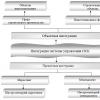
A typical scheme of a combined heating system with the connection of radiators and underfloor heating circuits. This is the most technologically advanced and easily customizable option, but it requires a significant initial investment. 1 - heating boiler; 2 - safety group, circulation pump, expansion tank; 3 - manifold for separate two-pipe connection of radiators according to the "star" scheme; 4 - heating radiators; 5 - underfloor heating manifold, includes: bypass, three-way valve, thermostatic head, circulation pump, combs for connecting floor heating circuits with gearboxes and flow meters; 6 - contours of the warm floor
There are quite big number variations in the execution of the boiler room piping, while in each individual case, its own principles of operation of the hydraulic system apply. However, if you do not take into account extremely specific options, then there are only five ways to coordinate the operation of heating devices of various types:
- Parallel binding of the underfloor heating collector to the mains of the heating unit. The tie-in point in the main line must be made up to the point of connection of the radiator network, the coolant supply is provided by an additional circulation pump.
- Association by type of primary and secondary rings. The main, wrapped in a ring, has several supply tie-ins in the supply part, the coolant flow in the connected circuits decreases as it moves away from the heating source. Flow balancing is performed by selection of the pump flow and flow limitation by regulators.
- Connection to the extreme point of the coplanar collector. The movement of the heat carrier in the underfloor heating loops is provided by a common pump located in the generator part, while the system is balanced according to the priority flow principle.
- Connection via a hydraulic separator is optimally suited for a large number of heating devices, a significant difference in flow rates in the circuits and a significant length of the underfloor heating loops. This option also uses a coplanar manifold, while a hydraulic arrow is needed to eliminate the pressure drop that interferes with the correct operation of the circulation pumps.
- Local parallel connection of the loop through the unibox. This option is well suited for connecting a short floor heating loop, for example, if necessary, heat the floor only in the bathroom.
The simplest option is to turn on the underfloor heating circuit to a radiator heating system with a coolant temperature of 70-80 ° C. 1 - line with supply and return of the high-temperature circuit; 2 - contour of the warm floor; 3 - unibox.
It must be remembered that the nature of the work of a warm floor can also vary depending on the layout of the coil. The “snail” scheme is considered optimal, in which the pipes are laid in pairs, which means that the entire area is heated almost evenly. If the warm floor is arranged in a “snake” or “maze”, then the formation of colder and warmer zones is practically guaranteed. This disadvantage can be eliminated, including due to the correct settings.
Temperature regime
Before proceeding with the adjustment of a warm floor, it is extremely important to establish a clear idea of \u200b\u200bthe purpose for which it is being performed. According to the principle of operation, a water-heated floor is fundamentally different from other heating devices. The main difference is the operating temperature of the coolant.
If the supply to the radiator network is carried out at temperatures up to 80 ° C, then the heating of the coolant entering the floor heating coil is limited to 40-42 ° C. This is necessary for reasons of comfort and safety. In normal mode, the temperature on the floor surface fluctuates in the range of 22-26 ° C, stronger heating causes discomfort.
There are two ways to control the heating temperature of a liquid underfloor heating. The first of them involves temperature control on the supply branch of the collector by mixing a portion of the cooled coolant from the return. Technically, this solution is implemented by installing a three-way valve with a thermostatic head RTL push-action. The difference between such a head and a radiator head is that it relies in operation on the temperature of the coolant, and not the air. With this method of regulation, the flow in the loops remains constant, only the temperature of the coolant changes with a small amplitude.
The second adjustment method involves limiting the flow of hot coolant in the circuit. In this case, a thermostatic head is also installed, but it is located on a two-way valve that interrupts the return flow circuit. With this method of regulation, the supply and return are connected by a bypass circuit, the flow through which is regulated by a restrictive valve with a pre-calibrated capacity.
The principle of such regulation is based on the high inertia of the underfloor heating system. During operation, the coolant is supplied to the loops at the nominal temperature of the heating unit, only the total flow changes periodically. Thus, the heating of the screed occurs cyclically, that is, a significant heat capacity of the storage layer is required to smooth out temperature drops.
In both cases, one important rule applies: thermostatic fittings must necessarily rely on the return temperature of the loop or collector. The device can have a mechanical or electronic principle of operation, it can even be a conventional thermometer. The need for a correct location is due to the fact that it is almost impossible to judge the effectiveness of the adjustment by the value of the coolant temperature at the supply, because the length of the loops can vary significantly.
Rules for refueling the system
It is impossible to set the operation of a warm floor if the coolant flow in the loops changes spontaneously. This phenomenon is typical in the presence of air congestion, so the heating system must not only be properly organized technically, but also properly charged.
To fully fill the system, automatic air vents must be installed on both branches of the underfloor heating collector. If the loops are located at a level above the collector, the supply connection to the latter must be made through a deaerator. Refueling of the underfloor heating system is carried out separately from other heating circuits, that is, the piping of the generator part and the radiator network must be filled in advance, and the shut-off valves at the collector inlets must be closed.
To fill the coolant into the system, a hose from the water supply system or pump is connected to the drainage outlet of the supply branch of the collector. Accordingly, a hose for bleeding air must be connected to a similar outlet of the return branch, the reverse end of which is either led out into the street or lowered into a container with a volume of 30-40 liters.
The collector and its piping are filled first in the underfloor heating system. In this case, the flow meters on the supply branch must be fully open, and the regulators on the return branch must be closed. Next, you need to sequentially fill each loop with coolant until a clean coolant without air bubbles flows from the bleed hose. Filling the warm floor is carried out at a minimum flow for uniform extrusion of air from the system. When all the underfloor heating loops are filled, you can put the heating system into operation and balance it.
Working with manifold meters
Hydraulic balancing of underfloor heating loops consists in rationing the flow in each coil. Depending on the length, a different amount of incoming coolant may be required in order for it to cool exactly to the calculated value when passing through the loop. The quantitatively required flow is determined as the ratio of the thermal load on the loop to the product of the heat capacity of water or other coolant and the temperature difference in the supply and return: G \u003d Q / s * (t 1 - t 2).
Often you can find recommendations to determine the flow rate of the coolant according to the performance of the circulation pump, that is, to divide its supply in proportion to the ratio of the lengths of the loops. Such advice should be avoided: in addition to the fact that it is quite difficult to calculate the length of each coil, one of the most important rules is violated - to choose equipment parameters based on the needs of the system, and not vice versa. Attempts to distribute the flow in the described way almost always lead to the fact that the flow in the loops differs significantly from the calculated values, which makes further adjustment of the system impossible.
The very same adjustment of the flow with flow meters is quite simple. In some models, the throughput is changed by turning the body, in others - by rotating the stem with a special key. The scale on the body of the flow meter indicates the flow rate in liters per minute, you just need to set the appropriate position of the float.
Almost always, when the throughput of one flow meter changes, the flow in the remaining loops changes, so the adjustment is carried out several times, successively calibrating each outlet. If such changes are especially pronounced, this indicates a lack of capacity of the control valves through which the collector is connected, or a too low performance of the circulation pump.
Automatic and manual temperature equalization
When adjusting the underfloor heating by mixing and limiting, the methods for setting the required coolant temperature are somewhat different. It also matters whether the proportional adjustment is performed on the fly, or whether the adjustment is carried out manually. The latter is permissible only for the mixing regulation method and only on condition that the coolant flow in the remaining circuits of the system changes insignificantly.
Manual setting of a three-way valve requires temperature control on the return branch, for which a thermometer sleeve or an attached temperature probe can be used.
Temperature measurements should not be carried out immediately, but based on the length of the loop and the flow rate of the coolant in it. It is necessary to measure the temperature after a time sufficient for 2 or 3-fold renewal of the coolant in the underfloor heating system.
The task of adjustment is to ensure a constant temperature difference of the coolant between the supply and return. In this case, the temperature difference is determined by the design of the warm floor and is calculated by the thickness, screed material, as well as the direction and step of laying the pipes of the coil.
Automatic proportional control is uncommonly easier. The main control element is a RTL thermostatic head or a unibox valve.
The higher the mark on which the flywheel is set, the higher the temperature of the coolant will be, which is true for both mixing and limiting control. published If you have any questions on this topic, ask them to specialists and readers of our project.
The traditional radiator heating of apartments, private properties, offices and other facilities has been replaced by underfloor heating. The heat carrier here is the energy of a liquid heated to the operating temperature (water, ethylene glycol solution, antifreeze) or electricity passing through a special cable, infrared film or carbon rods.
In most cases, such heating is equipped, combining it with a radiator heating system. Often underfloor heating is the only way to heat rooms to a comfortable temperature. The most popular is a warm water floor.
The principle of operation of the water floor is as follows:
- Under the finish coating, the floor is mounted with a set of necessary devices and components, through which water heated to a certain temperature circulates. It heats the finish coat and thus gives off heat to the room.
- Since the heat comes from below, the necessary level of humidity is provided, which has a positive effect on the comfortable stay of a person in such a room.
According to medical studies, it is established that the minimum temperature of the floor should be at least 26 0 C, and the maximum - 35 0 C. This is reflected in sanitary standards and rules. The maximum limitation is due to the fact that a higher heating temperature can adversely affect many finish coatings, as well as human well-being.
Creating such a floor is a rather difficult task. You must be able to carry out calculations, draw up diagrams, specifications necessary materials and accessories. In addition, you need to have the skills to work with many tools for correct and competent installation. If desired, a warm floor can be done with your own hands and set up its work yourself, armed with necessary knowledge.

The main components of a water floor are:
- Boiler of water heating type. For the heating system, its selection is carried out according to power. It should be 20% more than the total capacity of the serviced underfloor heating.
- Discharge type pump (circulation). It can be included in the design of the boiler, be its integral part, or it must be purchased separately and installed in the heating system.
If the area of the heated object is more than 120 m 2, then the circulation pump must be present in the water-type floor heating system.
- The tank is expansion. Must be present in the heating system to compensate for thermal expansion. The selection is carried out by capacity. It depends on the volume of the coolant in the pipe system of the floor. Typically, the volume of the expansion tank is 10% of the volume of the coolant poured into the system.
- Pressure gauge. The device controls the pressure in the system.
- Ball and shutoff valves. Ball valves are located at the inlet of the water heating boiler, and shut-off valves are located at the inlet and outlet. Shut-off valves are used for repair and maintenance work without draining the water from the entire system.
- Pipes. For laying the route under the finish coating, products made of polypropylene, including glass-reinforced, cross-linked polyethylene or metal-plastic, are used. Diameter 16÷20 mm. The requirements that apply to them are as follows: they must withstand a temperature of at least 95 0 C and a pressure of 10 bar. Usually such pipes are labeled "for heating". The pipes to be laid are attached to a special reinforcing mesh. They are fixed with clamps made of plastic in increments of 100 to 300 mm. Pipe laying options are very different. They can be laid in the form of a snake, a spiral, loops, a double snail, etc.

One circuit for heating two or more rooms of the object is not desirable; for each room, its own circuit must be calculated and executed.
- Collector. It is a device with which water is distributed through pipes (heating system circuit), as well as regulate and adjust the heating temperature of the coolant. This is a branch pipe with several outlets (up to 12 pcs.). Serves for connection of all mounted contours on object to one main line of supply of the warm and cooled coolant. The composition of the collector includes elements used to set up underfloor heating. Manufacturers produce products in a wide range. The simplest of them have only shut-off valves, the more complex ones are equipped with control valves, and the most advanced and modern ones have servo drives on the valves. This allows you to adjust the temperature by mixing the coolant heated with the liquid returning from the circuit and already cooled down. The latest devices operate automatically without human intervention.

The collector must be mounted in a special cabinet, which must be installed above the floor level, and pipes from it must not be discharged from above.
- Compression or Eurocone fittings. Serve for laying the pipeline route and connecting the collector to it.
Types of floor heating regulation
Water-type floor regulation means control of 2 parameters: floor temperature and room temperature. Moreover, if the first concept can be set and controlled in the process of work, then the second one directly depends on the temperature of the floor itself.
The principles of regulation are several methods that depend on the equipment, devices and instrumentation used for these purposes.
All methods are divided into the following types:
- manual;
- individual;
- group;
- complex.
Manual adjustment is carried out using thermal heads installed on the return and supply manifolds. Requires experience and time. The result appears after 3-4 hours. It has been experimentally established that if the temperature reaches 40-55 0 C at the entrance to the system, then 20-25 0 C are present in the room.
Individual regulation is carried out by installing the sensor in a warm floor. This allows you to control the required temperature in each individual room.
Group control is to obtain a floor temperature that will be the same in all rooms.
Comprehensive adjustment - a combination of individual and group, as well as competent selection and installation of the necessary equipment.
Temperature control
The temperature control of the heating water system is carried out using a manifold. It is desirable that it be with a flow meter if the goal is not only to obtain the desired temperature in the room, but also to save money. The device controls the flow of water or other coolant. When necessary, it works and shuts off the fluid supply.
How to adjust depends on the design of the device. Recommendations for setting up a floor heating collector are always indicated in the operating instructions and maintenance collector, as well as passport data, which a conscientious manufacturer always attaches to the product.
Installing a collector, where radiator heating is used, and at the same time a water-heated floor system is connected, requires not only correct installation, but also correct configuration. The temperature of the pipe system mounted in the floor cannot be as in. There it reaches 70-90 0 C, and this should not be in the pipes of the floor heating circuit. It is twice as low. The recommended floor temperature limits are in the range of 30-45 0 C.
The ways to adjust the floor heating collector are as follows:
- from the manufacturer (factory);
- unconventional.
Setting the floor heating collector from the manufacturer is an option when the temperature is controlled according to the factory instructions. Usually this is an automatic method, where heating is carried out in automatic or manual modes by special modules. They are assembled on a three-way valve.

The module consists of a thermometer that controls the temperature, a relay, a bypass and a circulation pump. By turning the knob/thermal head of the valve, you can decrease or increase the temperature value. The circulation pump is necessary for running water through the pipe circuit and taking part of the coolant from this circuit through the valve.

There are more modern models of collectors, the design of which provides for a thermostat or a servo drive.
To supply a coolant with the required parameters to the pipe system, a special line called a bypass line is used. It is a bypass line running on the collector. The three-way valve does not allow the entire coolant to pass through itself, but only a small amount. The rest flows through the bypass. There it is mixed with cold water coming from the collector, and then moves to the water heating unit. Without a bypass line, the normal operation of the underfloor heating is impossible.
In an unconventional way, setting the required temperature in the circuit will help install a thermostatic relay on the return line. It is installed on the collector. The operation of the circulation pump (switching on and off) installed on the manifold (on the supply or on the return line) occurs when the set temperature is reached or when it falls below the required value. The temperature is set on the relay using the handle in the range of 30-35 0 С.
The pump supplies liquid heated to 70 0 C and above into the pipe system, the heat is transferred to the base of the heated floor, as a result, after passing through the pipe circuit, the thermal switch is triggered and the pump turns off. Cooling of the liquid occurs in the collector. Upon reaching a temperature below the set one, the reverse process will occur: the pump will turn on and the coolant will heat up.
The simplest and cheapest way is to install a circulation pump and valve in the coolant supply system, and install an overhead thermostat on the return line to the collector. When the room warms up (this will be indicated by the temperature in the pipe system exceeding the set value), the thermostat will stop the supply of warm liquid and turn off the pump. When the temperature drops, it will turn on the pump again and supply hot heat carrier to the pipe system. Work is carried out in 2 modes - working and waiting.
The warm floor is also regulated by installing a mixing valve. Usually this is how the temperature of a water heated floor is regulated in an apartment located in high-rise building. It is connected to the central heating system of the house. Here, a circulation pump is installed at the supply, either a three-way valve or a mixing valve can be mounted in front of it.
The hot and cold coolant is mixed to the desired temperature. At the same time, attention must be paid to the setting of the mixing valve, in contrast to the three-way valve, which can be turned as you like.
The most expensive and rational method is to control the temperature by installing a special drive called a servo drive on the distributor, and a thermostat in the room. The last device is controlled by the operation of the servo. It opens and closes as the temperature drops or rises automatically.

Video
Having chosen water (hydraulic) underfloor heating as the main or additional heating option, it must be remembered that such a floor must be properly installed. Any errors in its device may lead to its improper functioning. Therefore, in order to get a durable heating system, it is best to turn to professionals and pay attention to the quality of its components. Much depends on the insulation of the base. Only in this case, a comfortable stay in the room will be ensured.
Read also...
- Symptoms of giardiasis in adults and methods of treatment
- Why dream of pregnancy: interpretation of sleep according to Vanga's dream book
- Giardiasis who treats. Treatment of giardiasis. The use of folk methods of treatment
- The use of folk remedies for sore throat Treatment of the throat at home with folk remedies