Assembling electrical panels with your own hands
This is a step-by-step practical instruction for those who want to learn how to assemble and switch a switchboard on their own. In the article, we tried to describe in detail all the key operations, paying special attention to the nuances that may be unknown to amateur electricians.
The assembly and disconnection of input distribution devices (ASU) is a multi-stage type of work, where each stage is extremely important, where there are no trifles. The shield must turn out to be safe and convenient for use, all its elements, combined into a system, must properly perform the functions assigned to them:
- energy control;
- consumer and chain management;
- provision of selectively triggered protection.
You can organize an electrical panel on your own, but for this, a home craftsman needs to have electrical skills above the minimum level. For the design of the ASP and the selection of components, it will not be superfluous to understand the processes and knowledge of the rules. Next, we will consider the assembly of electrical panels using the example of fairly branched systems in order to cover a wider range of issues.
We design an electrical panel
For a layman, this is best done when all the wires have already been laid and all the circuits have been accounted for. At the development stage, we must create working drawings for ourselves, according to which subsequent work will be carried out, and also found suitable specifications for components and accessories.
Consumer accounting, group creation
You need to start by compiling a complete list of consumers, if it was not done during the installation of the wiring. This will not include an iron or a sconce in the hallway, but each wire that comes to the board, which must be recorded and indicated by a number.
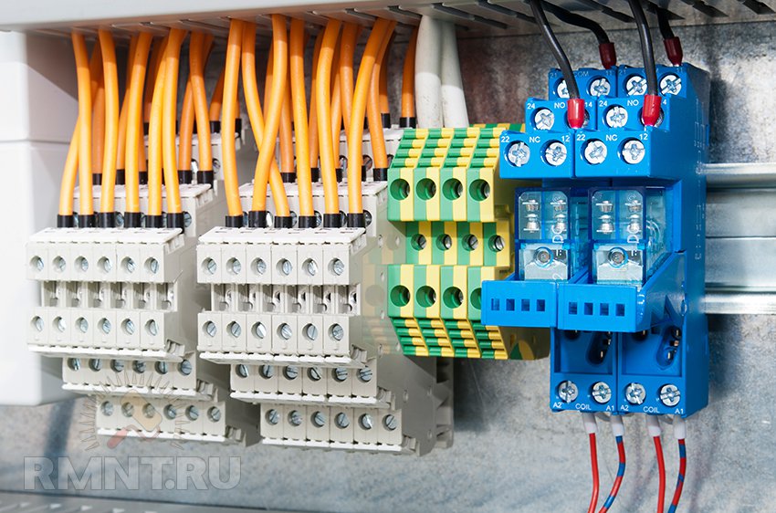
If, according to the scheme, it is supposed to connect more than two conductors to one modular device, then it is worth purchasing terminal blocks in order to make branching reliably and accurately. They can also be designed for DIN rail mounting.
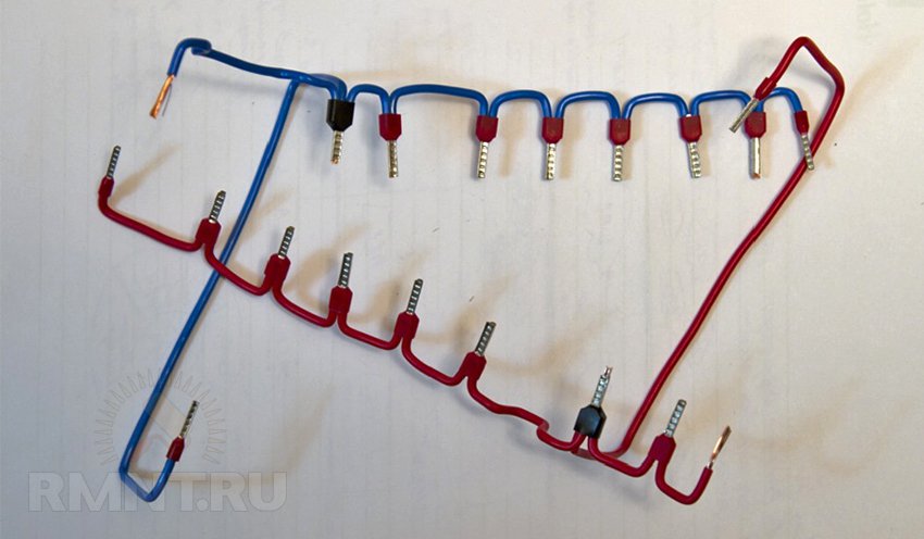
To transfer voltage between modular devices (RCDs, automatic devices) in the same row, it is convenient to use insulated combs. They provide good contact, withstand heavy loads, save time, and improve the ergonomics of the assembled switchboard. Combs are available in different lengths and cut as needed (also purchase side caps).
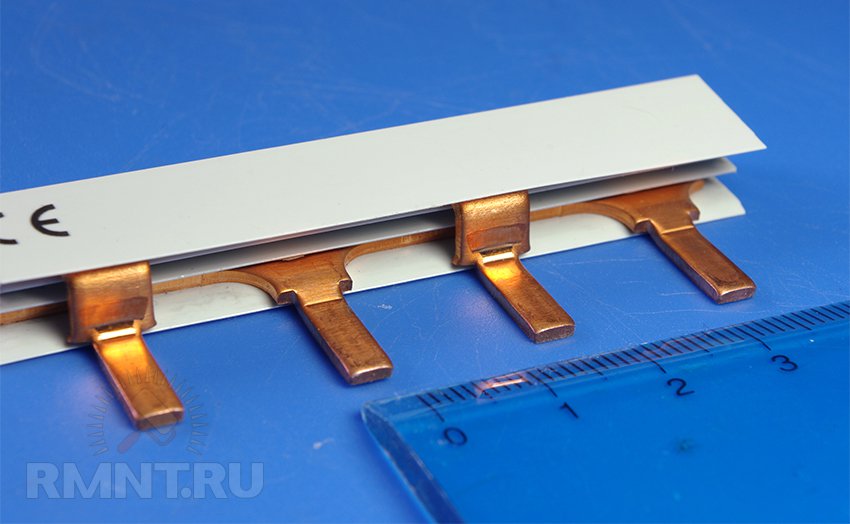
To connect multi-pole automation, there are combs for several independent rows.
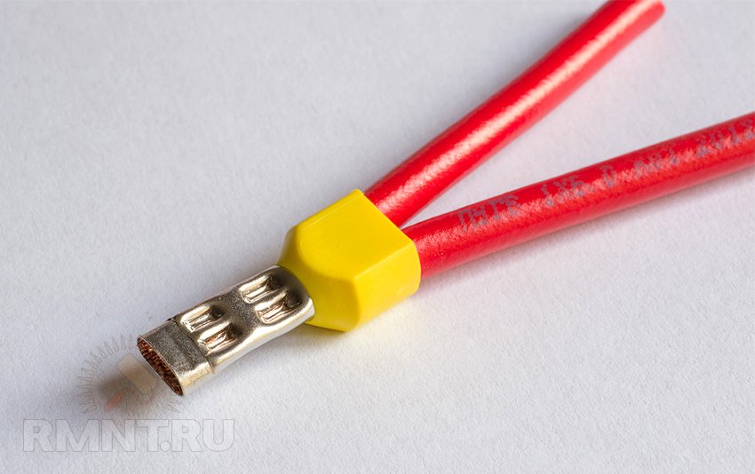
Between the rows of modular devices, the phase will have to be distributed with a piece of wire, then its stripped edge must be squeezed in the tip. Products with a length of a centimeter or more are better suited. To clamp two conductors in one machine, it is worth using double tips. There are models for 3 wires, for conductors of different cross-sections.
Assembling and disconnecting the switchboard
Before starting work, we recommend arranging emergency lighting for the working area (in extreme cases, use a headlamp when reconnecting). Use a table where you can lay out tools and accessories. Make some brackets on the wall to temporarily tie the wires that are not yet connected. In an easy-to-view place, hang the electrical panel assembly diagram. Check the completeness of the systems. Disconnect the lead-in cable.
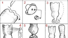
1. Assembly and preliminary assembly of the box
The flap housing should be prepared:
- we remove the plugs on the walls of the box (sometimes you have to cut out additional holes for entering wires);
- screw on DIN rails;
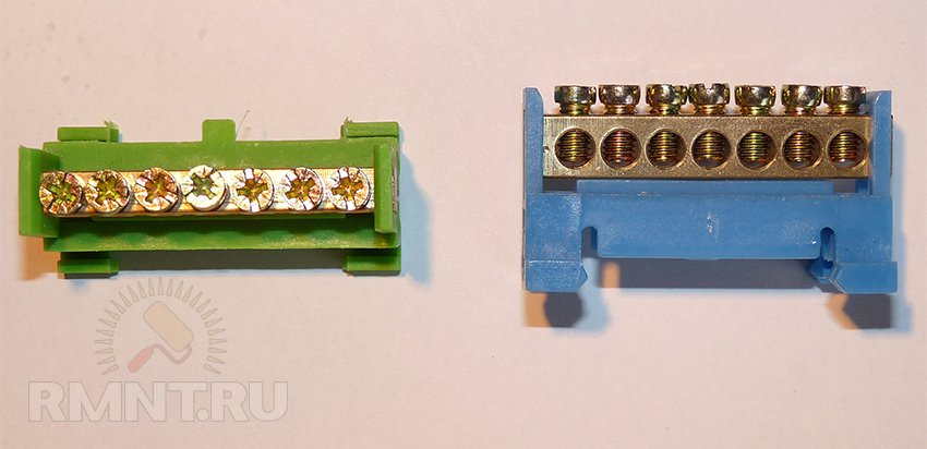
- we install on the walls of the neutral and ground bus;
- remove the door (if any);
- we connect the mounting brackets.
![]()
The built-in drawer can now be temporarily secured in place by checking the quality of the created niche. It is immediately removed so that it is convenient to deal with the wires, in addition, many professional electricians prefer to do part of the work at the workbench (you can put the automation on, open the necessary jumpers).
2. Prepare the wires
First you need to roughly adjust them in length. This is especially true if there is no cavity in the wall where excess wire can be placed (for example, if a niche is in brickwork). But you need a margin so that you can easily reach the most distant circuit breaker or bus.
Attention! Sometimes, if there are many consumers, it makes sense to lead some of the conductors into the box from above, and some from below. Therefore, group them according to this criterion and collect them in bunches.
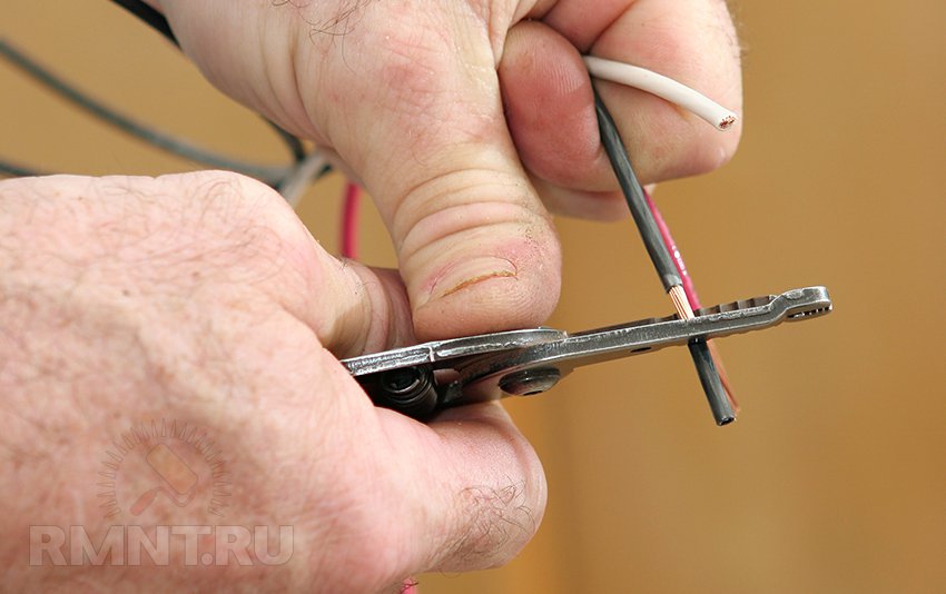
The outer insulation is now removed from the wiring cables. It is better to do this with a special tool that does not damage the primary insulation of the conductors.
It is necessary to clean it so far that at the entrance to the box the wire still remains with external insulation. Ideally, the corrugated channel (or pipe) should also enter.
Attention! When the outer insulation is removed, the marking is also lost (often the wires are simply signed with a marker on top during installation). Therefore, we recommend marking the conductors at the same time as cleaning. It is convenient to use masking tape, on which you can make any notes.
3. Installing the shield in place
We lay all the conductors and the lead-in cable inside. It makes sense to level the wires in one layer, it is advisable to take into account the arrangement of the machines (see the diagram) to which they will be connected.
4. Arrangement of modular devices on a DIN rail
We produce according to the scheme, we strictly observe the correspondence of the denominations. Usually, the RCD is first fixed, and immediately after it - its machines, at the end they have independent circuit breakers and other modular devices.
It is not necessary to install all the automatics at once, some craftsmen like to power the RCD and the automata alternately, as they are attached to the rail. At the same stage, the meter is mounted, if its place is in the shield.
5. Commutation
We connect the conductors of each circuit or a specific consumer to our machines and buses one by one. There are several important points here:
- we work in order, for example, from right to left;
- we bring the core to the fixation point and cut off the excess;
- we carry out the laying of wires in the shield horizontally and vertically, turns - only at right angles;
- if there is not enough space, or it is not possible to get wires from different sides of the box, you can go through the wires behind the DIN rail.
- we clean the ends of the wires from the main insulation by about 1 centimeter (we use a special tool);
- be sure to put on tips on soft cores;
- we make ends under the clamp of the machine and tighten the terminal tightly;
- we supply voltage to the machine from above, and connect the conductor from below (although most devices are two-sided, this is a generally accepted standard);
- tugging the wire with our hands, we check the reliability of fixation, while we pay attention that copper does not protrude above the machines, but the insulation is not clamped either;
- we collect the bundles of wires together with plastic ties and place them behind the rail.
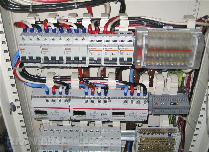
We distribute phase and zero between modular devices. Non-professionals usually have difficulties with RCD switching, how to do this can be seen on the shield diagram.
The main transfer in one row can be done with contact combs; in the absence of such, electricians sometimes use homemade jumpers. These should be rigid wires with a cross section of 4-6 squares.
6. Input connection
The lead-in cable is clamped on the main machine (phase and zero), and the grounding conductor goes directly to the bus. From the machine, the phase and zero go either to the counter, or are already distributed according to the scheme.
7. Final stage
If the wiring is ready, the consumers are connected and the wiring accessories are in place, then you can alternately apply the load to the individual lines. Each RCD is tested by pressing the corresponding button (the voltage in the controlled circuit must be disconnected). Power the entire system as long as there is no problem. Now it remains to mark the automation, attach a circuit to the door, install the covers on the dashboard body.
Competent and accurate assembly of electrical panels is the key to the durable operation of all wiring. But it is worth noting that you cannot save on components. High-quality automation from well-known manufacturers will avoid costly accidents and can save lives.
Turishchev Anton, rmnt.ru