Infrared security detectors. Passive infrared motion detectors. Difference between active and passive infrared sensors
How to fool an IR detector
The initial disadvantage of the IR passive motion detection method is that the person must be clearly different in temperature from the surrounding objects. At a room temperature of 36.6º, no detector will distinguish a person from the walls and furniture. Even worse: the closer the room temperature is to 36.6º, the worse the sensitivity of the detector. Most modern devices partially compensate for this effect by increasing the gain at temperatures from 30º to 45º (yes, the detectors also work successfully at the reverse temperature difference - if the room is +60º, the detector will easily detect a person, thanks to the thermoregulation system human body will keep the temperature around 37º). So, when the outside temperature is about 36º (which is often found in southern countries), the detectors open doors very poorly, or, on the contrary, due to extremely high sensitivity, they react to the slightest breath of wind.
Moreover, the IR detector can be easily blocked by any object room temperature(sheet of cardboard) or wear a thick fur coat and hat so that your arms and face do not stick out, and if you walk slowly enough, the IR detector will not notice such small and slow disturbances.
There are also more exotic recommendations on the Internet, such as a powerful IR lamp, which, if turned on slowly (with a regular dimmer), will drive the IR detector off scale, after which you can walk in front of it even without a fur coat. Here, however, it should be noted that good IR detectors in this case will give a malfunction signal.
Finally, the most well-known problem with IR detectors is masking. When the system is disarmed, during business hours during the day, you, as a visitor, come to the desired premises (a store, for example) and, seizing the moment while no one is looking, block the IR detector with a piece of paper, cover it with an opaque self-adhesive film, or fill it with spray paint. This is especially convenient for a person who works there himself. The storekeeper carefully blocked the detector during the day, climbed through the window at night, took everything out, and then removed everything and called the police - horror, they robbed, but the alarm did not work.
To protect against such masking, the following technical techniques exist.
1. In combined (IR + microwave) sensors, it is possible to issue a fault signal if the microwave sensor detects a large reflected radio signal (someone came very close or reached out directly to the detector), and the IR sensor stopped producing signals. In most cases in real life this does not mean the malicious intent of the criminal, but the negligence of the staff - for example, a high stack of boxes blocked the detector. However, regardless of malicious intent, if the detector is blocked, this is a disorder, and such a “malfunction” signal is very appropriate.
2. Some control panels have a control algorithm when, after disarming the detector, it detects movement. That is, the absence of a signal is considered a malfunction until someone passes in front of the sensor and it issues a normal “there is movement” signal. This function is not very convenient, because often all premises are disarmed, even those that no one is going to enter today, but it turns out that in the evening, in order to arm the premises again, you will have to go into all the rooms where no one was there during the day, and wave your hands in front of the sensors - the control panel will make sure that the sensors are operational and will graciously allow you to arm the system.
3. Finally, there is a function called “near zone”, which was once included in the requirements of the Russian GOST and which is often mistakenly called “anti-masking”. The essence of the idea: the detector should have an additional sensor looking straight down, under the detector, or a separate mirror, or a special tricky lens, in general, so that there is no dead zone below. (Most detectors have a limited viewing angle and generally face forward and 60 degrees downward, so there is a small dead zone directly below the detector, at floor level about a meter from the wall.) It is believed that a cunning enemy will somehow be able to get into this dead zone and from there block (mask) the lens of the IR sensor, and then brazenly walk around the entire room. In reality, the detector is usually installed so that there is no way to get into this dead zone without bypassing the sensor's sensitivity areas. Well, perhaps through the wall, but additional lenses will not help against criminals penetrating through the wall.
Radio interference and other interference
As I said, the IR sensor operates close to its sensitivity limit, especially with room temperatures approaching 35º C. Of course, it is also very susceptible to interference. Most IR detectors can give a false alarm if you place a cell phone near it and call it. At the connection establishment stage, the phone emits powerful periodic signals with a period close to 1 Hz (it is in this range that typical signals from a person walking in front of the IR sensor lie). A few watts of radio emission are quite comparable to microwatts thermal radiation person.
In addition to radio emissions, there may also be optical interference, although the lens of the IR sensor is usually opaque in the visible range, but powerful lamps or 100 W car headlights in the neighboring spectral range can again quite produce a signal comparable to microwatts from a person in the desired range. The main hope is that extraneous optical interference, as a rule, is poorly focused and therefore equally affects both sensitive elements of the IR sensor, thus the detector can detect the interference and not issue a false alarm.
Ways to improve IR sensors
For ten years now, almost all IR security detectors contain a fairly powerful microprocessor and therefore have become less susceptible to random interference. Detectors can analyze the repeatability and characteristic parameters of the signal, long-term stability of the background signal level, which has significantly increased immunity to interference.
IR sensors, in principle, are defenseless against criminals behind opaque screens, but are susceptible to the influence of heat flows from climate control equipment and extraneous illumination (through a window). Microwave (radio) motion sensors, on the contrary, are capable of producing false signals, detecting movement behind radio-transparent walls, outside the protected premises. They are also more susceptible to radio interference. Combined IR + microwave detectors can be used both according to the “AND” scheme, which significantly reduces the likelihood of false alarms, and according to the “OR” scheme for especially critical premises, which practically eliminates the possibility of overcoming them.
IR sensors cannot distinguish little man from a big dog. There are a number of sensors in which sensitivity to the movements of small objects is significantly reduced through the use of 4-area sensors and special lenses. In this case, the signal from a tall person and from a short dog can be distinguished with some probability. You need to understand well that it is, in principle, impossible to completely distinguish a crouched teenager from a Rottweiler standing on its hind legs. Nevertheless, the likelihood of a false alarm can be significantly reduced.
A few years ago, even more complex sensors appeared - with 64 sensitive areas. In fact, this is a simple thermal imager with an 8 x 8 element matrix. Equipped with a powerful processor, such sensors (calling them a “detector” would be too much to say) are capable of determining the size and distance to a moving warm target, the speed and direction of its movement - 10 years ago such sensors were considered the pinnacle of technology for homing missiles, but are now used for defense from common thieves. Apparently, we will soon get used to calling small robots that wake you up at night with the words “IR sensor” with the words: “Sorry, sir, but thieves, sir, they want tea. Should I serve them tea now or ask them to wait while you wash up and take your revolver?”
Currently, passive electro-optical infrared (IR) detectors occupy a leading position when choosing to protect premises from unauthorized intrusion at security facilities. Aesthetic appearance, ease of installation, configuration and maintenance often give them priority over other detection means.
Passive optical-electronic infrared (IR) detectors (they are often called motion sensors) detect the fact of human penetration into the protected (controlled) part of the space, generate an alarm signal and, by opening the contacts of the executive relay (monitoring station relay), transmit an “alarm” signal to the warning equipment . Terminal devices (TD) of notification transmission systems (TPS) or a fire alarm control panel (PPKOP) can be used as warning devices. In turn, the above-mentioned devices (CU or Control Panel) transmit the received alarm notification via various data transmission channels to the central monitoring station (CMS) or local security console.
The operating principle of passive optical-electronic IR detectors is based on the perception of changes in the level of infrared radiation of the temperature background, the sources of which are the human body or small animals, as well as all kinds of objects in their field of vision.
Infrared radiation is heat that is emitted by all heated bodies. In passive optical-electronic IR detectors, infrared radiation hits a Fresnel lens, after which it is focused on a sensitive pyroelectric element located on the optical axis of the lens (Fig. 1).

Passive IR detectors receive streams of infrared energy from objects and are converted by a pyroelectric receiver into an electrical signal, which is sent through an amplifier and a signal processing circuit to the input of the alarm driver (Fig. 1)1.
In order for an intruder to be detected by a passive IR sensor, the following conditions must be met:
- . the intruder must cross the beam of the sensor sensitivity zone in the transverse direction;
. the offender’s movement must occur within a certain speed range;
. The sensitivity of the sensor must be sufficient to register the difference in temperature between the surface of the intruder’s body (taking into account the influence of his clothing) and the background (walls, floor).
Passive IR sensors consist of three main elements:
- . an optical system that forms the directional pattern of the sensor and determines the shape and type of the spatial sensitivity zone;
. a pyro receiver that registers human thermal radiation;
. signal processing unit of the pyro receiver, which separates signals caused by a moving person from the background of interference of natural and artificial origin.
Depending on the design of the Fresnel lens, passive optical-electronic IR detectors have different geometric dimensions of the controlled space and can be either with a volumetric detection zone, or with a surface or linear one. The range of such detectors ranges from 5 to 20 m. Appearance These detectors are shown in Fig. 2.

Optical system
Modern IR sensors are characterized by a wide variety of possible radiation patterns. The sensitivity zone of IR sensors is a set of rays of various configurations diverging from the sensor in radial directions in one or several planes. Due to the fact that IR detectors use dual pyroelectric receivers, each beam in the horizontal plane is split into two:

The detector sensitivity zone can look like:
- . one or several narrow beams concentrated in a small angle;
. several narrow beams in the vertical plane (radial barrier);
. one wide beam in the vertical plane (solid curtain) or in the form of a multi-fan curtain;
. several narrow beams in a horizontal or inclined plane (surface single-tier zone);
. several narrow beams in several inclined planes (volumetric multi-tiered zone).
. In this case, it is possible to change in a wide range the length of the sensitivity zone (from 1 m to 50 m), the viewing angle (from 30° to 180°, for ceiling sensors 360°), the angle of inclination of each beam (from 0° to 90°), the number rays (from 1 to several dozen).
The variety and complex configuration of the forms of the sensitivity zone are primarily due to the following factors:
- . the desire of developers to ensure versatility when equipping rooms with different configurations - small rooms, long corridors, the formation of a specially shaped sensitivity zone, for example with a dead zone (alley) for pets near the floor, etc.;
. the need to ensure uniform sensitivity of the IR detector over the protected volume.
It is advisable to dwell on the requirement of uniform sensitivity in more detail. The signal at the output of the pyroelectric detector, all other things being equal, is greater, the greater the degree of overlap by the intruder in the detector’s sensitivity zone and the smaller the beam width and distance to the detector. To detect an intruder at a large (10...20 m) distance, it is desirable that the beam width in the vertical plane does not exceed 5°...10°; in this case, the person almost completely blocks the beam, which ensures maximum sensitivity. At shorter distances, the sensitivity of the detector in this beam increases significantly, which can lead to false alarms, for example, from small animals. To reduce uneven sensitivity, optical systems are used that form several oblique beams, while the IR detector is installed at a height above human height. The total length of the sensitivity zone is thereby divided into several zones, and the beams “closest” to the detector are usually made wider to reduce sensitivity. This ensures almost constant sensitivity over distance, which on the one hand helps to reduce false alarms, and on the other hand increases detection ability by eliminating dead zones near the detector.
When constructing optical systems of IR sensors, the following can be used:
- . Fresnel lenses - faceted (segmented) lenses, which are a plastic plate with several prismatic lens segments stamped on it;
. mirror optics - several specially shaped mirrors are installed in the sensor, focusing thermal radiation onto the pyroelectric detector;
. combined optics using both mirrors and Fresnel lenses.
. Most PIR sensors use Fresnel lenses. The advantages of Fresnel lenses include:
. simplicity of the design of a detector based on them;
. low price;
. the ability to use one sensor in different applications using interchangeable lenses.
Typically, each segment of the Fresnel lens forms its own beam of the radiation pattern. Usage modern technologies lens manufacturing makes it possible to ensure almost constant sensitivity of the detector for all rays due to the selection and optimization of the parameters of each lens segment: segment area, angle of inclination and distance to the pyro receiver, transparency, reflectivity, degree of defocusing. IN Lately The technology for manufacturing Fresnel lenses with complex precise geometry has been mastered, which gives a 30% increase in the collected energy compared to standard lenses and, accordingly, an increase in the level of useful signal from a person at long distances. The material from which modern lenses are made provides protection for the pyro receiver from white light. Unsatisfactory operation of the IR sensor can be caused by such effects as heat flows resulting from heating of the electrical components of the sensor, insects falling on sensitive pyroelectric detectors, and possible re-reflections of infrared radiation from the internal parts of the detector. To eliminate these effects, the latest generation of IR sensors use a special sealed chamber between the lens and the pyro-receiver (sealed optics), for example, in the new IR sensors from PYRONIX and C&K. According to experts, modern high-tech Fresnel lenses are practically not inferior in their optical characteristics to mirror optics.
Mirror optics as the only element of an optical system are used quite rarely. IR sensors with mirror optics are produced, for example, by SENTROL and ARITECH. The advantages of mirror optics are the ability to focus more accurately and, as a result, increase sensitivity, which allows you to detect an intruder at long distances. The use of several specially shaped mirrors, including multi-segment ones, makes it possible to provide almost constant distance sensitivity, and this sensitivity at long distances is approximately 60% higher than for simple Fresnel lenses. Using mirror optics, it is easier to protect the near zone located directly below the sensor installation site (the so-called anti-sabotage zone). By analogy with replaceable Fresnel lenses, IR sensors with mirror optics are equipped with replaceable detachable mirror masks, the use of which allows you to select the required shape of the sensitivity zone and makes it possible to adapt the sensor to various configurations of the protected premises.
Modern high-quality IR detectors use a combination of Fresnel lenses and mirror optics. In this case, Fresnel lenses are used to form a sensitivity zone at medium distances, and mirror optics are used to form an anti-tamper zone under the sensor and to provide a very long detection distance.
Pyro receiver:

The optical system focuses IR radiation on a pyroelectric receiver, which in IR sensors uses an ultra-sensitive semiconductor pyroelectric converter capable of recording a difference of several tenths of a degree between the temperature of a person’s body and the background. The temperature change is converted into an electrical signal, which, after appropriate processing, triggers an alarm. IR sensors usually use dual (differential, DUAL) pyroelements. This is due to the fact that a single pyroelement reacts in the same way to any temperature change, regardless of what it is caused by - the human body or, for example, heating a room, which leads to an increase in the frequency of false alarms. In a differential circuit, the signal of one pyroelement is subtracted from another, which makes it possible to significantly suppress interference associated with changes in background temperature, as well as significantly reduce the influence of light and electromagnetic interference. The signal from a moving person appears at the output of the double pyroelectric element only when the person crosses the beam of the sensitivity zone and is an almost symmetrical bipolar signal, close in shape to the period of a sinusoid. For this reason, the beam itself for a double pyroelectric element is split into two in the horizontal plane. In the latest models of IR sensors, in order to further reduce the frequency of false alarms, quadruple pyroelements (QUAD or DOUBLE DUAL) are used - these are two dual pyroelectric sensors located in one sensor (usually placed one above the other). The observation radii of these pyro receivers are made different, and therefore a local thermal source of false alarms will not be observed in both pyro receivers at the same time. In this case, the geometry of the placement of pyro receivers and their connection circuit is selected in such a way that signals from a person are of opposite polarity, and electromagnetic interference causes signals in two channels of the same polarity, which leads to the suppression of this type of interference. For quadruple pyroelements, each beam is split into four (see Fig. 2), and therefore the maximum detection distance when using the same optics is approximately halved, since for reliable detection a person must, with his height, block both beams from two pyroelectric detectors. The detection distance for quadruple pyroelements can be increased by using precision optics that form a narrower beam. Another way to correct this situation to some extent is the use of pyroelements with complex intertwined geometry, which the PARADOX company uses in its sensors.
Signal processing block
The signal processing unit of the pyro receiver must ensure reliable recognition of a useful signal from a moving person against a background of interference. For IR sensors, the main types and sources of interference that can cause false alarms are:
- . heat sources, air conditioning and refrigeration units;
. conventional air movement;
. solar radiation and artificial light sources;
. electromagnetic and radio interference (vehicles with electric motors, electric welding, power lines, powerful radio transmitters, electrostatic discharges);
. shocks and vibrations;
. thermal stress of lenses;
. insects and small animals.
The processing unit's identification of a useful signal against a background of interference is based on an analysis of the signal parameters at the output of the pyroelectric detector. These parameters are the signal size, its shape and duration. The signal from a person crossing the beam of the IR sensor sensitivity zone is an almost symmetrical bipolar signal, the duration of which depends on the speed of movement of the intruder, the distance to the sensor, the width of the beam, and can be approximately 0.02...10 s with a recorded range of movement speeds of 0 ,1…7 m/s. Interference signals are mostly asymmetrical or have a different duration from the useful signals (see Fig. 3). The signals shown in the figure are very approximate; in reality, everything is much more complicated.
The main parameter analyzed by all sensors is the signal magnitude. In the simplest sensors, this recorded parameter is the only one, and its analysis is carried out by comparing the signal with a certain threshold, which determines the sensitivity of the sensor and affects the frequency of false alarms. In order to increase resistance to false alarms, simple sensors use a pulse counting method, which counts how many times the signal exceeded the threshold (that is, in essence, how many times the intruder crossed the beam or how many beams he crossed). In this case, an alarm is not issued the first time the threshold is exceeded, but only if, within a certain time, the number of exceedances becomes greater than a specified value (usually 2...4). The disadvantage of the pulse counting method is the deterioration of sensitivity, which is especially noticeable for sensors with a sensitivity zone such as a single curtain and the like, when an intruder can only cross one beam. On the other hand, when counting pulses, false alarms are possible due to repeated interference (for example, electromagnetic or vibration).
In more complex sensors, the processing unit analyzes the bipolarity and symmetry of the signal shape from the output of the differential pyroelectric receiver. The specific implementation of such processing and the terminology used to refer to it1 may vary from manufacturer to manufacturer. The essence of the processing is to compare a signal with two thresholds (positive and negative) and, in some cases, to compare the magnitude and duration of signals of different polarities. A combination of this method with separate counting of excesses of positive and negative thresholds is also possible.
Analysis of the duration of signals can be carried out either by a direct method of measuring the time during which the signal exceeds a certain threshold, or in the frequency domain by filtering the signal from the output of the pyro receiver, including using a “floating” threshold, depending on the range of frequency analysis.
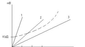
Another type of processing designed to improve the performance of IR sensors is automatic thermal compensation. In the ambient temperature range of 25°C...35°C, the sensitivity of the pyro receiver decreases due to a decrease in the thermal contrast between the human body and the background; with a further increase in temperature, the sensitivity increases again, but “with the opposite sign.” In so-called “conventional” thermal compensation circuits, the temperature is measured, and when it increases, the gain is automatically increased. “True” or “two-way” compensation takes into account the increase in thermal contrast for temperatures above 25°C...35°C. The use of automatic temperature compensation ensures almost constant sensitivity of the IR sensor over a wide temperature range.
The listed types of processing can be carried out by analogue, digital or combined means. Modern IR sensors are increasingly using digital processing methods using specialized microcontrollers with ADCs and signal processors, which allows for detailed processing of the fine structure of the signal to better distinguish it from the background noise. Recently, there have been reports of the development of completely digital IR sensors that do not use analog elements at all.
As is known, due to the random nature of useful and interfering signals, the best processing algorithms are those based on the theory of statistical solutions.
Other protection elements for IR detectors
IR sensors intended for professional use use so-called anti-masking circuits. The essence of the problem is that conventional IR sensors can be disabled by an intruder by first (when the system is not armed) taping or painting over the input window of the sensor. To combat this method of bypassing IR sensors, anti-masking schemes are used. The method is based on the use of a special IR radiation channel, which is triggered when a mask or reflective obstacle appears at a short distance from the sensor (from 3 to 30 cm). The anti-masking circuit operates continuously while the system is disarmed. When the fact of masking is detected by a special detector, a signal about this is sent from the sensor to the control panel, which, however, does not issue an alarm until the time comes to arm the system. It is at this moment that the operator will be given information about masking. Moreover, if this masking was accidental (a large insect, the appearance of a large object for some time near the sensor, etc.) and by the time the alarm was set it had cleared itself, the alarm signal is not issued.
Another security element that almost all modern IR detectors are equipped with is a contact tamper sensor, which signals an attempt to open or break into the sensor housing. The tamper and masking sensor relays are connected to a separate security loop.
To eliminate IR sensor triggering from small animals, either special lenses with a dead zone (Pet Alley) from floor level to a height of about 1 m are used, or special signal processing methods are used. It should be taken into account that special signal processing allows animals to be ignored only if their total weight does not exceed 7...15 kg, and they can approach the sensor no closer than 2 m. So if there is a jumping cat in a protected area, then such protection will not will help.
To protect against electromagnetic and radio interference, dense surface mounting and metal shielding are used.
Installation of detectors
Passive optical-electronic IR detectors have one remarkable advantage over other types of detection devices. It is easy to install, configure and Maintenance. Detectors of this type can be installed either on a flat surface of a load-bearing wall or in the corner of a room. There are detectors that are placed on the ceiling.
A competent choice and tactically correct use of such detectors are the key to reliable operation of the device, and the entire security system as a whole!
When choosing the types and number of sensors to ensure the protection of a particular object, one should take into account the possible routes and methods of penetration of an intruder, the required level of detection reliability; costs for the acquisition, installation and operation of sensors; features of the object; performance characteristics sensors A feature of IR passive sensors is their versatility - with their use it is possible to block a wide variety of rooms, structures and objects from approaching and entering: windows, showcases, counters, doors, walls, ceilings, partitions, safes and individual objects, corridors, room volumes. Moreover, in some cases, a large number of sensors will not be required to protect each structure; it may be sufficient to use one or several sensors with the required sensitivity zone configuration. Let's take a look at some of the features of using IR sensors.
The general principle of using IR sensors is that the rays of the sensitivity zone should be perpendicular to the intended direction of movement of the intruder. The sensor installation location should be chosen so as to minimize dead zones caused by the presence of large objects in the protected area that block the beams (for example, furniture, houseplants). If doors in a room open inwards, the possibility of masking an intruder should be taken into account open doors. If dead spots cannot be eliminated, multiple sensors should be used. When blocking individual objects, the sensor or sensors must be installed so that the rays of the sensitivity zone block all possible approaches to the protected objects.
The range of permissible suspension heights specified in the documentation (minimum and maximum heights) must be observed. This especially applies to radiation patterns with inclined beams: if the suspension height exceeds the maximum permissible, this will lead to a decrease in the signal from the far zone and an increase in the dead zone in front of the sensor, but if the suspension height is less than the minimum permissible, this will lead to a decrease in range detection while simultaneously reducing the dead zone under the sensor.
1. Detectors with a volumetric detection zone (Fig. 3, a, b), as a rule, are installed in the corner of the room at a height of 2.2-2.5 m. In this case, they evenly cover the volume of the protected room.
2. Placing detectors on the ceiling is preferable in rooms with high ceilings from 2.4 to 3.6 m. These detectors have a denser detection zone (Fig. 3, c), and their operation is less affected by existing furniture.

3. Detectors with a surface detection zone (Fig. 4) are used to protect the perimeter, for example, non-permanent walls, door or window openings, and can also be used to limit access to any valuables. The detection zone of such devices should be directed, as an option, along a wall with openings. Some detectors can be installed directly above the opening.

4. Detectors with a linear detection zone (Fig. 5) are used to protect long and narrow corridors.
Interference and false positives
When using passive optical-electronic IR detectors, it is necessary to keep in mind the possibility of false alarms that occur due to various types of interference.
Interference of a thermal, light, electromagnetic, or vibration nature can lead to false alarms of IR sensors. Despite the fact that modern IR sensors have a high degree of protection from these influences, it is still advisable to adhere to the following recommendations:
- . To protect against air flows and dust, it is not recommended to place the sensor in close proximity to sources of air flows (ventilation, open window);
. Avoid direct exposure of the sensor to sunlight and bright light; when choosing an installation location, the possibility of exposure to light for a short time early in the morning or at sunset, when the sun is low above the horizon, or exposure to the headlights of vehicles passing outside should be taken into account;
. During arming, it is advisable to turn off possible sources of powerful electromagnetic interference, in particular light sources not based on incandescent lamps: fluorescent, neon, mercury, sodium lamps;
. to reduce the influence of vibrations, it is advisable to install the sensor on capital or supporting structures;
. It is not recommended to point the sensor at heat sources (radiator, stove) and moving objects (plants, curtains), towards the presence of pets.
Thermal interference - caused by heating of the temperature background when exposed to solar radiation, convective air flows from the operation of radiators of heating systems, air conditioners, and drafts.
Electromagnetic interference - caused by interference from sources of electrical and radio emissions to individual elements of the electronic part of the detector.
Extraneous interference - associated with the movement of small animals (dogs, cats, birds) in the detector detection zone. Let us consider in more detail all the factors affecting the normal operation of passive optical-electronic IR detectors.
Thermal interference
This is the most dangerous factor, which is characterized by changes in the ambient temperature background. Exposure to solar radiation causes local increase temperatures of individual sections of the walls of the room.
Convective interference is caused by the influence of moving air flows, for example from drafts with an open window, cracks in window openings, as well as during the operation of household appliances. heating devices- radiators and air conditioners.
Electromagnetic interference
They occur when any sources of electrical and radio radiation are turned on, such as measuring and household equipment, lighting, electric motors, and radio transmitting devices. Strong interference can also be caused by lightning strikes.
Extraneous interference
Small insects such as cockroaches, flies, and wasps can be a unique source of interference in passive optical-electronic IR detectors. If they move directly along the Fresnel lens, a false alarm of this type of detector may occur. The so-called house ants, which can get inside the detector and crawl directly on the pyroelectric element, also pose a danger.
Installation errors
A special place in the incorrect or incorrect operation of passive optical-electronic IR detectors is occupied by installation errors when performing work on installing these types of devices. Let us pay attention to striking examples of incorrect placement of IR detectors in order to avoid this in practice.

In Fig. 6 a; 7 a and 8 a show the correct, correct installation of detectors. You only need to install them this way and no other way!

In Figures 6 b, c; 7 b, c and 8 b, c present options for incorrect installation of passive optical-electronic IR detectors. With this installation, real intrusions into protected premises may be missed without issuing an “Alarm” signal.

Do not install passive optical-electronic detectors in such a way that they are exposed to direct or reflected rays of sunlight, as well as the headlights of passing vehicles.
Do not direct the detector detection zone at the heating elements of heating and air conditioning systems, at curtains and curtains that may sway due to drafts.
Do not place passive optical-electronic detectors near sources of electromagnetic radiation.
Seal all holes of the passive optical-electronic IR detector with the sealant supplied with the product.
Destroy insects that are present in the protected area.
Currently, there is a huge variety of detection tools, differing in operating principle, scope, design and performance characteristics.
Right choice A passive optical-electronic IR detector and its installation location are the key to reliable operation of the security alarm system.
When writing this article, materials were used, among other things, from the magazine “Security Systems” No. 4, 2013
For the purpose of protecting property, a large range of various technical means is used, among which security detectors occupy a special place.
Security detectors are a kind of “sensitive receptors” of the security alarm system, which are designed to detect a criminal in a protected area, generate an alarm signal and transmit it to the security system for response measures.
The safety of the client’s property, and in some cases, the safety of his life and health, directly depends on which detectors are used in the security system of an office or apartment.
The operation of detectors is based on the use of various physical principles. There are 2 main types of detectors:
1. Passive detectors, which themselves are not sources of waves of various physical natures (electromagnetic, acoustic, etc.).
2. Active detectors, which are sources of such waves.
The obvious advantages of passive detectors are their environmental friendliness and low energy consumption. However, in a number of cases, in particular, to increase the reliability of the alarm signal generated by the detector and minimize the number of false alarms, detectors of the second type are used. At the same time, in modern detectors, as a rule, active and passive methods of operation are combined in one device.
Based on the physical principle of operation, detectors can be divided into the following groups.
Infrared - detectors that detect thermal (infrared) radiation from the human body and generate an alarm signal when the source of thermal radiation moves.
Ultrasonic - detectors that emit ultrasonic vibrations and receive a signal reflected from surrounding objects. An alarm signal is generated if movement occurs in the controlled area.
Radio wave - detectors emitting in the range of ultrashort radio waves. Their operating principle is similar to that of ultrasonic detectors.
Barometric - detectors that generate an alarm signal when there is an abrupt drop in atmospheric pressure in a protected area, which can occur if a door or window is opened.
Acoustic - detectors that generate an alarm signal when a characteristic sound is detected in a protected area. Most often this is the sound of window glass breaking.
Seismic - detectors installed on a wall or other structure and generating an alarm signal if characteristic vibrations are detected in this structure, occurring when an attempt is made to destroy a barrier using known methods and tools (jackhammer, abrasive tool, gas cutter, “oxygen lance”, explosives, etc.) .P.).
Inertial - detectors in which an alarm signal is generated using the inertial properties of objects and, as a rule, under mechanical influence on a protected object, for example a car (swinging, jolting). The inertial group includes vibration and shock contact detectors.
Piezoelectric - various detectors that use piezoelectric materials in their work, which have the property of inducing a potential difference on opposite sides of the piezoelectric crystal when it is deformed. Piezoelectric ones include contact detectors for monitoring glass breakage, detectors for monitoring the immobility of installed (sculpture) or suspended (paintings) objects, etc.
Magnetic contact detectors are detectors that generate an alarm signal when the reed switch opens due to the removal of a magnetic element from it.
They are usually installed on windows and entrance doors.
Electrical contact detectors are detectors that generate an alarm signal when an electrical contact is opened. Currently, they are usually used in alarm systems and operate in manual mode.
Combined - detectors that combine two or more physical principles of operation (infrared and ultrasonic, infrared and radio wave, acoustic and magnetic contact, etc.). The use of two physical principles of operation often makes it possible to increase the noise immunity of the detector and eliminate false alarms.
Ultrasonic and radio wave detectors are classified as active, while all others are classified as passive detectors.
In addition to those indicated, there are detectors that use other physical principles of operation: capacitive, inductive, electromagnetic, etc.
It is necessary to add to the above that infrared and radio wave detectors can be single-position (to control movement in a certain volume) and two-position (to control movement through a fence). Two-position detectors consist of a structurally separate transmitter and receiver of electromagnetic waves and are used to protect perimeters; The formation of an alarm signal in them occurs when a person crosses an infrared or radio beam. IN in this case we are dealing with an active infrared detector.
This article will discuss the operating principle and design features of passive infrared detectors, which are rightfully very popular among consumers and are the most common.
Passive infrared detectors are designed to detect a person within the detection zone. The main task of the detector is to detect infrared radiation from the human body. As can be seen from Figure 1, the thermal radiation of the human body is within the spectral range of electromagnetic radiation with wavelengths of 8-12 microns. This is the so-called equilibrium glow of the human body, the maximum radiation length of which is completely determined by temperature and for 37°C corresponds to approximately 10 microns. There are a number of physical principles and corresponding devices that are used to detect radiation in the specified spectral range. For passive infrared detectors, a sensing element with optimal ratio sensitivity/cost. Such a sensitive element is a pyroelectric photocell.
Rice. 1. Spectral dependence of the glow intensity: the sun, a fluorescent lamp, an incandescent lamp, the human body and the transmission spectrum of a number of filters blocking visible light: a silicon filter, a clear silicon filter, a filter with a cut-off wavelength of 5 μm, and a filter with a cut-off wavelength of 7 μm.
The phenomenon of pyroelectricity consists in the appearance of an induced potential difference on opposite sides of a pyroelectric crystal during non-equilibrium short-term heating. Over time, electrical charges from external electrical circuits and redistribution of charges inside the crystal lead to relaxation of the induced potential. From the above it follows:
interrupt frequency (Hz).

Rice. 2. Dependence of the magnitude of the pyroelement response signal on the interruption frequency of the recorded thermal IR signal.
1. For effective pyroelectric registration of thermal radiation, it is necessary to use a chopper with an optimal radiation interruption frequency of about 0.1 Hz (Fig. 2). On the other hand, this means that if a lensless design of a pyroelectric element is used, it will be able to register a person only when he enters the radiation pattern (Fig. 3, 4) and when leaving it at a speed of 1 - 10 centimeters per second.

Rice. 3, 4. Shape of the radiation pattern of a paired packaged pyroelectric element in the horizontal (Fig. 3.) and vertical (Fig. 4.) planes.
2. To increase the sensitivity of the pyroelectric element to the magnitude of the temperature difference (the difference between the background temperature and the temperature of the human body), it is necessary to design it to maintain the minimum possible dimensions in order to reduce the amount of heat required for a given increase in the temperature of the sensitive element. The size of the sensing element should not be excessively reduced, as this will lead to an acceleration of the relaxation characteristics, which is equivalent to a decrease in sensitivity. Exists optimal size. The minimum sensitivity is usually 0.1°C for a 1 x 2 mm pyroelectric element with a thickness of several microns.
3. To increase the thermal stability of the detector and cut off the influence of slowly changing ambient temperature, the sensitive element is made in the form of a pair structure of electrically back-to-back elements located on a common substrate. The appearance of the sensitive pyroelectric element is shown in Fig. 5. As can be seen from the figure, the sensitive element is manufactured in a typical housing of a conventional semiconductor electronic element. A window is formed in the housing from a material that does not transmit radiation from the outside with a wavelength of less than 1 - 7 microns, depending on the type of filter material used (see Fig. 1). The world leader in the production of pyroelectric elements is HAMAMATSU (Japan). In Ukraine, pyroelements are produced by SKTB of the Institute of Physics of the National Academy of Sciences of Ukraine.

Rice. 5. Appearance of the sensitive element of a pyroelectric passive IR detector.
You can clearly formulate the conditions for detecting a person using an infrared detector. The infrared detector is designed to detect moving objects with a temperature different from the background value. Range of recorded movement speeds: 0.1 - 1.5 m/sec. Thus, the infrared detector does not register stationary objects, even if their temperature exceeds the background level (a stationary person) or if an object with a temperature different from the background moves in such a way that it does not cross the sensitive zones of the detector (for example, moves along the sensitive zone).
Naturally, the high sensitivity of the infrared detector is achieved by using a lens system for concentrating incoming radiation (Fig. 6). In an infrared detector, the lens system performs two functions.

Rice. 6. Options for forming the radiation pattern of IR detectors depending on the type of lens system.
Firstly, the lens system serves to focus the radiation on the pyroelectric element.
Secondly, it is designed to spatially structure the sensitivity of the detector. In this case, spatial zones of sensitivity are formed, which usually have the shape of “petals”, and their number reaches several tens. An object is detected whenever it enters or exits sensitive areas.
Typically, the following types of sensitivity diagram are distinguished, which is also called the radiation diagram.
1). Standard - fan-shaped in azimuth and multi-tiered in elevation (Fig. 6a).
2). Narrow-beam - single- or double-beam, long-range in azimuth and multi-tiered in elevation (Fig. 6b).
3). Curtain-like - narrowly directed in azimuth and fan-shaped in elevation (Fig. 6c).
There is also a circular radiation pattern (in particular, for detectors installed on the ceiling of a room), as well as a number of others.
Let's consider design options for the beamforming system (Fig. 7). This optical system can be either a lens or a mirror. Manufacturing a conventional lens system to meet the requirement of forming a spatially structured radiation pattern is an expensive task, so conventional lenses are not used in passive infrared sensors. So-called Fresnel lenses are used. A conventional lens uses a special spherical surface shape to deflect light directionally (focusing), and the lens material has an optical refractive index that is different from the refractive index of the surrounding medium. The Fresnel lens uses the phenomenon of diffraction, which manifests itself in particular in the deflection of a light beam when passing through a narrow slit. The Fresnel lens is made by stamping and is therefore inexpensive. The disadvantage of using a Fresnel lens is the inevitable loss of half the radiation energy as a result of its diffraction deflection by the lens in a direction other than the direction toward the pyroelectric element.

Rice. 7. Design options for security passive infrared detectors: with a Fresnel lens and with a mirror focusing system.
A mirror lens is more efficient than a Fresnel lens. It is made from plastic by stamping, followed by coating the structured surface with a reflective coating that does not change its properties over time (up to 10 years). The best coating is gold. Hence the higher, approximately twice the cost of passive infrared detectors with a mirror system compared to a lens system. In addition, detectors with a mirror system are larger in size compared to detectors equipped with Fresnel lenses.
Why are more expensive detectors with a mirror system for concentrating incoming radiation used? The most important characteristic of a detector is its sensitivity. The sensitivity is almost the same per unit area of the detector input window. This means, in particular, that if a passive infrared detector is designed with hypersensitivity, then we are forced to increase the size of the radiation concentration zone - the area of the entrance window, and, therefore, the detector itself (the maximum sensitivity of modern passive infrared detectors makes it possible to detect a person at a distance of up to 100 meters). If we assume that there is a loss of the useful signal due to the imperfection of the lens, then it is necessary to increase the gain electronic circuit processing the electrical signal generated by the sensitive element. Assuming the same sensitivity, the gain electrical diagram in a mirror detector is two times less than in a detector with a Fresnel lens. This means that detectors with a Fresnel lens are more likely to cause false alarms due to interference in the electronic circuitry.
Let's return once again to the optical design of the detector. In addition to the lens system and the optical “cutting” filter installed directly in the housing of the sensitive element, to reduce false alarms caused by various radiation sources, various optical filter elements are used (“white” filter, “black” mirror, etc.), task which minimize the entry of extraneous optical radiation onto the surface of the pyroelectric element.
The entrance window of most IR detectors is made in the form of a “white” filter. This filter is made of a material that scatters visible light, but at the same time does not affect the propagation of infrared radiation.
In detectors with a mirror system for concentrating incoming radiation, an additional absorption filter is placed directly on the mirror. Such a mirror perfectly reflects IR radiation and effectively absorbs the visible part of the spectrum. It is black in appearance because it does not reflect visible light, and is therefore called a “black” mirror. The use of an additional absorbing filter in relation to the one directly placed on the body of the photosensitive element makes it possible to reduce the thermal load on the sensitive element from the absorbed energy of the radiation incident on it, since the additional absorbing filter and the sensitive pyroelectric element are spatially separated.
Fresnel lenses are also being improved. Primarily by giving the lens a spherical shape, which minimizes aberrations compared to the standard cylindrical shape. In addition, additional structuring of the radiation pattern in the vertical plane is used due to the multifocal geometry of the lens: in the vertical direction, the lens is divided into three sectors, each of which independently collects radiation onto the same sensitive element.
The problem of counteracting the physical shielding of a detector, which boils down to installing a screen in front of it that blocks its “field of view” (so-called “masking”), is very relevant. Technical means to counter masking constitute the detector anti-masking system. Some detectors are equipped with built-in IR LEDs. If an obstacle appears in the detection zone of the detector, and therefore in the range of the LEDs, then the reflection of the LED radiation from the obstacle is perceived by the detector as an alarm signal. Moreover, periodically (in existing models - once every 5 hours) the detector self-tests for the presence of reflected radiation from IR LEDs. If during self-testing the required signal does not appear at the output of the electrical circuit, an alarm signal generation circuit is triggered. Detectors with anti-masking and self-testing functions are installed at the most critical facilities, in particular where it is possible to counteract the operation of the security system.
Another way to increase the noise immunity of a detector is to use a quadratic sensitive pyroelectric element together with the use of microprocessor signal processing. Different companies solve the problem of creating a quadratic element in different ways. For example, the OPTEX company uses two conventional double pyroelements located side by side. The main task of the system is to identify and “weed out” events caused by simultaneous illumination of both pyroelements (for example, headlights) or electrical interference.
The ADEMCO company uses a special design of a quadruple pyroelectric receiver, where four sensitive elements are located in one housing. In this case, pyroelements located both in the horizontal and vertical planes are connected back to back. Such a detector will not respond to small animals (mice, rats), which are often found in warehouses and are one of the reasons for false alarms (Fig. 8). The use of multi-polar connections of sensitive elements in such a detector makes “noise” false alarms impossible.

Rice. 8. Operation of a multi-channel noise pulse selection system using the example of the operation of a quadratic security passive IR detector.
ADEMCO is so confident in the perfection of the quadratic detector it has developed that it has announced a bonus payment if the owner of the detector records a false alarm.
Another precaution is the use of conductive film coatings applied to the inside surface of the entrance window to counteract radio frequency interference.
An effective method of increasing the noise immunity of detectors is the use of the so-called “dual technology”, which consists of using a combined detector that implements passive infrared and active radio wave (sometimes ultrasonic) operating principles.
The radio wave (ultrasonic) unit detects the presence of a Doppler shift in the frequency spectrum of the reflected radio signal (ultrasound), caused by the movement of the object. The use of such detectors is most effective with subsequent microprocessor processing of incoming signals. These detectors are not recommended for use in rooms where people are present, as the radiation has a harmful effect on health.
“Dual technology” detectors are used to protect premises where there are small pets: cats, dogs, as well as when there are periodically switched on stationary heat-emitting devices in the protected premises: a fax machine, a heater, a fan, etc.
We looked at the basic operation and design of passive infrared security detectors. In general, all constructive tricks used by certain companies have one goal - to reduce the likelihood of a false alarm, since a false alarm leads to unjustified costs of responding to an alarm, and also entails moral damage for the owner of the protected property.
Detectors are constantly being improved. On modern stage The main directions for improving detectors are to increase their sensitivity, reduce the number of false alarms, and differentiate moving objects based on authorized or unauthorized presence in the detection zone.
As a source of electrical signal, each sensitive pyroelectric element is also a source of random noise signals. Therefore, the task of minimizing fluctuation interference, which can be solved by circuit technology, is relevant. Are used different methods noise control.
Firstly, electronic discriminators of the input signal at the upper and lower levels are installed in the detector, which minimizes the frequency of interference (Fig. 9).

Rice. 9. Threshold system for two-way limitation of the noise signal level of a passive infrared security detector.
Secondly, a mode of synchronous accounting of pulses arriving through both optical channels is used. Moreover, the circuit is designed in such a way that a useful optical signal at the input leads to the appearance of a positive electrical pulse in one channel and a negative one in the other. The output uses a subtraction circuit. If the signal source is a noise electrical signal, it will be identical for the two channels and there will be no resulting signal at the output. If the signal source is an optical signal, the output signal will be summed.
Thirdly, the pulse counting method is used. The essence of this method is that a single object registration signal does not lead to the formation of an alarm signal, but sets the detector into the so-called “pre-alarm state”. If within a certain time (in practice it is 20 seconds) the object registration signal is not received again, the pre-alarm state of the detector is reset (Fig. 10).

Rice. 10. Operation of the pulse counter system.
As a rule, all detectors require a 12 V electrical supply. direct current. The current consumption of a typical detector is in the range of 15 - 40 mA. An alarm signal is generated and transmitted to the security control panel via an output relay with normally closed contacts.
The industry produces detectors for installation indoors, as well as in open areas; the latter have the appropriate climatic design. The typical service life of passive infrared detectors is 5 - 6 years.
IR motion sensor
One of the innovations that has entered our lives, its scope is wide, so it ceased to be a “curiosity” and began to be used everywhere. Naturally, people are interested in this device. I managed to find a publication by the author, who covered this topic in great detail; as they say, neither add nor subtract.
I present to your attention article from the magazine “Radioamator” author N.P. Vlasyuk, Kyiv City.
Passive infrared motion sensor
A passive infrared motion sensor powered by ~220 V is supplied complete with a halogen spotlight and is designed as a single device. It is called passive because it does not illuminate the controlled area with infrared radiation, but uses its background infrared radiation, and therefore is absolutely harmless.
Purpose of IR sensor and practical application
The sensor is designed to automatically turn on a load, for example a spotlight, when a moving object enters its control zone and turn it off after the object leaves the zone. It is used to illuminate the facades of houses, utility yards, construction sites, etc.
Technical data of PIR sensor model 1VY7015
The supply voltage of the sensor and the entire device is ~220 V, the current consumption of the sensor itself in security mode is 0.021 A, which corresponds to a power consumption of 4.62 W. Naturally, when you turn on a 150 or 500 W halogen lamp, the power consumption increases accordingly. Maximum detection radius of a moving object (ahead of the sensor) 12 m, sensitivity zone in the horizontal plane 120...180 0, adjustable lighting delay (after the object leaves the control zone) from 5... 10 s to 10... 15 min. The permissible operating temperature range is -10…+40°С. Permissible humidity up to 93%.
The IR sensor can be in one of the following modes. “Security mode”, in which it “vigilantly” monitors the controlled area and is ready to turn on the executive relay (load) at any time. “Alarm mode”, in which the sensor, using an executive relay, turned on the load, since a moving object entered its controlled zone. “Sleep mode”, in which the sensor, being in the on state (under current), during the daytime, does not respond to external stimuli, and with the onset of twilight (darkness) it automatically switches to “Security mode”. This mode is designed to avoid turning on the lighting during the daytime. After power is applied, the sensor starts in “Alarm Mode” and then goes into “Security Mode”.
Similar sensors are also sold separately. They are used much more widely than a kit (spotlight with sensor), and according to the power supply mode, they can be designed for a voltage of ~220 V or = 12 V.
Working principle of a passive infrared sensor
The background infrared radiation of the controlled area is focused by the front glass (lens) onto a phototransistor sensitive to infrared rays. The low voltage coming from it is amplified with the help of operational amplifiers (op-amps) of the microcircuit included in the sensor circuit. Under normal conditions, the electromechanical load switch relay is de-energized. As soon as a moving object appears in the controlled area, the illumination of the phototransistor changes, and it outputs a changed voltage to the input of the op-amp. The amplified signal throws the circuit out of balance, triggering a relay that turns on a load, such as a lighting lamp. As soon as the object leaves the zone, the lamp continues to glow for some time, depending on the set time of the electronic time relay, and then goes into its initial state - “Security mode”.
The schematic diagram of the model 1VY7015 passive infrared sensor is shown in Fig. 1.

Compared to similar 1 2V IR sensors, the circuitry of this model is simple. It is drawn according to the wiring diagram. Since the manufacturers did not indicate all the radio elements on the wiring diagram, the author had to do this himself. On a board measuring 80x68 mm, mounted radio elements are placed without the use of CHIP elements.
Purpose of the main radio elements of the circuit diagram
1. The sensor power supply unit is transformerless, made using a quenching capacitor C2 with a capacity of 0.33 μF × 400 V. After the rectifier bridge, the zener diode ZD (1 N4749) sets a voltage of 25 V, which is used to power the winding of relay K1, and the stabilizer DA1 (78L08 ) from 25 V stabilizes 8 V, which is used to power the LM324 chip and the entire circuit in general. Capacitor C4 is a smoothing capacitor, and SZ protects the sensor from high-frequency interference.
2. Three-terminal infrared phototransistor PIR D203C is the “watchful eye” of the sensor, its main element, it is the one that issues the “command” to turn on the executive relay when the infrared background of the controlled area quickly changes. Powered by +8 V through resistor R15. Capacitor C13 is a smoothing capacitor, and C12 protects the phototransistor from high-frequency interference.
3. LM324N chip (market value $0.1) - the main amplifier of the sensor. It consists of 4 op-amps, which are connected in series (4-3-2-1) by the sensor circuit (radio elements R7, C6; D1, D2; R21, D3), which ensures high amplification of the signal produced by the IR phototransistor and high sensitivity of the entire sensor. It is powered by 8 V (“plus” - pin 4, “minus” - pin 11).
4. The purpose of the electromechanical relay K1 model LS-T73 SHD-24VDC-F-A is to turn on the load, or rather, to supply ~220 V to it. The +25 V voltage to the relay winding is supplied by transistor VT1. The rated operating voltage of the relay winding is 24 V, and its contacts, according to the inscription on the case, allow a current of 10 A at ~ 240 V, which raises doubts about the ability of such a small-sized relay to switch a load of 2400 W. Foreign manufacturers often overestimate the parameters of their radioelements.
5. Transistor VT1 type SS9014 or 2SC511. Main limit parameters: Uke.max=45 V, lk.max=0.1 A. Provides switching on/off of relay K1 depending on the voltage ratios (pin 1 of LM324N and collector VT2) on its base.
6. Bridge (R5, R6, R7, VR2, CDS photoresistor) transistor VT2 (SS9014, 2SC511) are designed to establish one of two operating modes of the sensor: “Security mode” or “Sleep mode”. The required mode is ensured by the illumination of the CDS photoresistor (it is this that, with its resistance changing with the illumination, indicates to the sensor whether it is day or night by the position of the variable resistor slider VR2 (DAY LIGHT). So, when the variable resistor slider is in the “Day” position, the sensor operates as day and night, and in the “Night” position - only at night, and during the day it is in “sleep” mode.
7. An adjustable electronic time relay (C14, R22 VR1) provides a time delay for turning off the luminous lamp from 5... 10 s to 10... 15 min after the object leaves the controlled area. Adjustment is provided
variable resistor TIME VR1.
8. Variable resistor SENS VR3 regulates the sensitivity of the sensor by changing the depth of negative feedback in op amp No. 3.
9. The damper circuit R1C1 absorbs voltage surges that occur when the halogen lamp is turned on/off.
10. The remaining radio elements (for example, R16-R20 R11, R12, etc.) ensure the normal operation of the op-amp of the LM324N chip.
When starting to repair the IR sensor, you should remember that all its radioelements are under phase voltage, which is life-threatening. When repairing such devices, it is recommended to turn them on via an isolation transformer. The sensor works reliably and rarely needs repairs, but if it is damaged, the repair begins with an external inspection of its circuit board. If no damage is found, then you should check the output voltages of the power supply (25 and 8V). The power supply device, and any other element of the circuit (microcircuit, transistors, stabilizer, capacitors, resistors), can fail due to voltage surges in the supply network or lightning strikes, and protection against them, unfortunately, is not provided in the sensor circuit . The tester can check the serviceability of all these elements, except for the microcircuit. If you suspect that it is not working, the microcircuit can be replaced. The weak link in the sensor may be the contacts of relay K1, since they switch significant inrush currents of the halogen lamp; their performance is checked with a tester.
Setting up the IR sensor consists of correctly installing three adjustment resistors located at the bottom of the sensor (Fig. 2).

What do these resistors regulate?
TIME - adjusts the delay time for turning off the halogen lamp after the object that caused it to turn on has left the controlled area. Adjustment range from 5...10 s to 10...15 min.
DAY LIGHT - sets the sensor to “Security Mode” or “Sleep Mode” during the daytime. From a physical point of view, the position of the variable resistor slider allows or prohibits the sensor from operating under certain lighting conditions. Adjustable illumination range 30 lux. So, if the regulator is turned counterclockwise (set to the “crescent” sign), then the sensor works only in the dark, and “sleeps” during the day. If you turn it to its extreme counterclockwise position (the “little sun” sign), the sensor works both during the day and at night, i.e. all day long. In an intermediate position between these values, the sensor can switch to “Security Mode” already at dusk. The sensor switches to one of the above modes automatically.
SENS - adjusts the sensitivity of the sensor, i.e. sets a larger or smaller area (or range) of the controlled zone.
Disadvantages of the IR sensor
The disadvantages of the ~220 V IR sensor are its false alarms. This occurs when branches of trees or bushes located in a controlled area move; from a passing car, or more precisely, from the heat of its engine; from a changing heat source, if it is located under the sensor; from sudden changes in temperature due to gusts of wind; from lightning and car headlights from the passage of animals (dogs, cats); When the power supply blinks, the sensor is triggered and the lamp continues to light for some time. The disadvantages of the sensor described above include its non-operating state in the absence of voltage ~220 V. The number of false alarms can be reduced by changing the position of the sensor.
The purpose of the front glass is the lens of the IR sensor. To expand the monitored area to Control 120° and even 180°, the sensor lens is made semicircular or spherical. During its manufacture (casting), numerous rectangular lenses are provided on its inner side. They divide the controlled sector into small areas. Each lens, from its own section, focuses infrared radiation into the center of the phototransistor. Dividing the controlled zone into sections leads to the fact that the controlled zone becomes fan-shaped (Fig. 3).

As a result, the sensor “sees” the intruder only in the black zone, and in the white zone it is “blind”. These zones, depending on the number and size of the lenses, have a configuration specified by the designers. The use of microprocessors makes it possible to eliminate a number of the above-described disadvantages of these sensors. The lens is the most important element of the IR sensor. It depends on it how wide the sensor “sees” horizontally and vertically. Some IR sensors have interchangeable lenses that create a monitored area for a specific task. The lens glass must be intact (not broken), otherwise the configuration of its controlled area is unpredictable.
1.Lighting of various rooms, i.e. automatic switching on/off of lighting in entrances, warehouses, apartments (houses), farm yards and farms. To do this, depending on the situation, you can use either the above-described sets of IR sensors with spotlights or separately sold sensors. Install the kit on stationary objects at a height of 2.5...4.5 m (Fig. 4).


Separately sold passive infrared sensors can be designed for a power supply voltage of either ~220 V or +12 V. For lighting, it is better to use ~220 V sensors; they are relatively cheap and also supply ~220 V to the load, so it is easy to connect light bulbs to them .
One of the variants of such a sensor, model USA 1009, is shown in Fig. 6.

It contains only two adjustment resistors: Time Delay, which regulates the time the load is turned off after the object leaves the controlled area, and Light Control, which allows or prohibits the operation of the sensor during the daytime. The maximum permissible load is 1200 W. The viewing angle of the controlled area is 180°, and its maximum length is 12 m.
Three colored wires come out of the sensor, intended for connecting the network and load. In Fig.7

shows a diagram for connecting such a sensor to a separate ~220 V lamp, which can also be used as a table lamp.
When connecting the sensor to the existing electrical wiring of the house (apartment), i.e. For already installed light bulbs and switches, it is important to correctly find the common wire of the sensor and combine it with the electrical wiring. Figure 8, a, b shows diagrams of the electrical wiring section before turning on the sensor and after turning it on.

If you use a sensor to illuminate the porch of a house, then it is better to install the sensor itself near the light bulb.
The use of IR sensors in lighting circuits significantly saves energy and creates convenience when they are automatically turned on/off.
2. Automatic switching on of lighting in apartments and houses. In such a situation, it is better to adapt the sensor to table lamp, so that if you don’t need it you can easily turn it off.
3. Notifying the owner of the house about the arrival of guests. In this case, the sensor must be directed to the fence gate or the space near it, and for sound notification, use a bell or other sound detector powered by ~220 V.
4. Security of the household yard, garage, farm, office, apartment. For this purpose, you can also use the above-described cheap IR sensors powered by ~220 V. However, such sensors have a big drawback: if the network goes out, they do not work, so they are used only for protecting unimportant objects. IR sensors powered from +12 V do not have these disadvantages, since they are easily provided with backup power from batteries. For this purpose, a small reception area has been developed - control device(PKP), which is mounted on the wall. It houses the power supply, 12 V 4 Ah or 7 Ah batteries and electronic components. All sensors of the protected object are connected to one control panel, which provides them with reliable power supply, receives alarm signals from them and transmits them to security. In the absence of security, you can connect a powerful sound siren to the control panel, which will scare away intruders. Thus, to protect important objects, control panel kits with 12 V IR sensors should be used; a standard 4-wire cable is pulled between them (two wires for 12 V power, two for an alarm signal). External adjustment resistors are not installed on +12 V IR sensors, since some of their functions are transferred to the “electronic filling” of the control panel device.
To protect your yard, IR sensors must be installed so that they are not noticeable, otherwise they may be damaged. To do this, IR sensors can be installed near windows inside the house, pointing their lens at the protected objects. For the protection of apartments and offices IR sensors They are installed in the corner of rooms, and to protect garages and farms, their lenses are directed at the entrance gate.
As already noted, cheap IR sensors for ~220 V and 12 V have a number of disadvantages, such as the sensor triggering when dogs, cats, or mice pass by. To eliminate this phenomenon, it is necessary to install an IR sensor inside the house on the window sill, direct it to the yard and place a protective screen in front of it (Fig. 9).

In this case, a “blind zone” is formed between the ground and the IR sensor’s capture zone, in which the sensor does not respond to small intruders, but it will react to a passing person, since the person is higher in height than this zone.
In the new 12 V sensors, designers, by complicating the circuit and design of the sensor, eliminated this drawback. Thus, the Israeli IR sensor Crow SRX-1100 has a microprocessor added and a microwave radio emitter installed, which determines the size of the intruder, compares it with the established thresholds and decides whether or not to give a command to the alarm.
Designers from Japan and other countries decided this problem another way. They provided for a displacement (inside the IR sensor) of the electronic board with the phototransistor up or down relative to the focusing point of the glass lenses. As a result, the black sensitive segments closest to the ground are cut off, and a “blind zone” is established near the ground, in which the sensor “does not see” small animals. The height of the blind spot can be adjusted by the same displacement of the electronic board. There are other ways to prevent IR sensors from responding to the passage of small animals. The problem of the IR sensor being triggered when it is illuminated by lightning or car headlights has been resolved. Naturally, all these improvements make passive IR sensors more expensive, but they increase the reliability of security.
One of the most popular elements of security systems is a volumetric passive infrared detector. This is explained by the very wide range of applications of such devices. They can be used both to control the internal volume of premises and to organize perimeter security. The Sintez Security company invites you to buy such equipment from us. We guarantee high quality, and also that the price of the products will be quite affordable.
How do passive infrared detectors work?
The functioning of such devices is based on recording changes in the infrared temperature background emanating from a variety of heated objects and, first of all, living bodies. Depending on the operating principle, sensors are divided into active and passive. In the latter, streams of infrared energy flow through the lens into a sensitive pyroelectric element.
Passive IR detectors are triggered if, when examining sectors of the controlled area, temperature changes are detected. They indicate the presence of movement in the sensor operating area. There are several types of such equipment, differing in their ability to record a certain speed of movement.
After the built-in microprocessor has analyzed the incoming data, the contact network opens or closes. This leads to the formation of an alarm message sent to the security console. Depending on the type of detection zone, the following are distinguished:
- linear;
- surface;
- volumetric passive IR detector.
What are the advantages of a passive volumetric IR detector?
This equipment is considered one of the most effective and has a number of advantages compared to surface and linear models. The reason for this is that when scanning rooms, the device studies them not only in the vertical direction (from floor to ceiling), but also in the horizontal plane. As a result, the reliability of the system increases significantly.
Volumetric sensors are classified as passive devices. Most often they are used to ensure security indoors. When designing systems using such equipment, it is necessary to take into account the fact that for devices of this type any obstacle is opaque. As a result, unique “dead” zones appear. This feature is not necessarily regarded as a disadvantage. Thanks to it, you can avoid reacting to a moving object outside the protected area.
If you choose such devices, the Sintez Security company recommends that you consider a number of parameters. These include:
- detection zone opening angle;
- sensor operating range.
Moreover, it should be taken into account that the equipment range parameter is indicated along the main axis. Along the lateral axes this figure will be lower. In addition, when setting up the system, you must also specify the correct temperature range. It differs significantly in heated and unheated rooms, for example. The company “Sintez Security” will help you make a smart choice. Contact us, express your wishes, and we will take care of the rest.
From us you can buy IR passives at a low price - there are 40 pieces in the catalog, compare, study the characteristics.