Monolithic reinforced concrete frame. Reinforced concrete frame of one-story industrial buildings
Reinforced concrete frames are designed for the construction of low-rise and multi-story civil (including residential) and industrial buildings with standard loads of 1 m 2 of ceilings from 3 to 30 kPa. The magnitude of the load depends on the span of the crossbar, the step of the columns, floor slabs, the method of construction, structural features of the frames.
Reinforced concrete frames are divided into:
By the method of providing spatial rigidity for structural-static types: frame, link, frame-link;
By construction technology: prefabricated, monolithic, precast monolithic;
By type of horizontal load-bearing structures: with beam ceilings, bezelless, with ceilings on trusses (including floor height).
11.2.1. Frameworks with beam ceilings
The design of prefabricated frame buildings is based on unified structural solutions provided by the catalogs of industrial serial products (for example, series 1.020.1-2s / 89, TK1-2). This practice is accepted in Russia and other countries. Some series are interspecific - for use in civil and industrial construction. Unification is carried out on the basis of the methodology of an open typing system and is based on typed dimensional schemes of the geometric parameters of buildings.
As a result of unification, the following main parameters frame buildings and their reinforced concrete elements:
Heights of typical floors: 3.0; 3.3; 3.6; 4.2; 5.4; 6.0; 7.2 m;
The height of the first elevated floor: 4.2 (with a typical floor height of 3.3 m); 4.8 (3.6); 6.0 (4.8); 7.2 (6.0) m;
The height of the basement floors: 3.2; 3.4; 3.7; 4.0; 4.6 m;
The height of the technical floor is 2.4 m;
The height of the technical underground is 2.0 m;
The heights of the upper hall floors: 4.2; 4.8; 5.4; 6.0; 7.0; 8.0 m;
Section of columns 400x400 mm;
Column height: on the 1st, 2nd and 3rd floors;
Prefabricated and precast monolithic crossbars with a section height of 450, 600 and 900 mm with a rigid or articulated connection to the column;
Floor slabs: multi-hollow (height 220 mm); ribbed (300 and 400 mm); ribbed type "TT" and "T" (600 mm);
Placement of staircases in the modular cells of columns with dimensions of 3.0x (6.0; 6.6; 7.2) m; 2.4x (4.8; 5.4; 6.0; 6.6) m.
Prefabricated Frame Elements. Of great importance in the mass construction of frame buildings are division methods bearing structures on prefabricated elements (Fig. 12.43). The partitioning system in many respects depends on the manufacturability of the construction, the cost of manufacturing elements at the plant and installation at the construction site, the operational properties of the joints and the reliability of the entire building.
Fig. 12.43. Methods for dividing reinforced concrete frames into prefabricated elements: a - two-story columns and single-span beams; b - single-story columns and single-span beams; c - T- and T-shaped columns and crossbars; g - T-shaped elements; d - H-shaped frames; e - the same with external consoles; g - U-shaped frames and crossbars-inserts; h - two-story frames and crossbars; and, k - cruciform elements; l - U-shaped elements; m - the same with internal consoles; n - T- and T-shaped elements; o - L-shaped elements; p, p - two-span frames
When developing reinforced concrete frames, they seek to enlarge products, reduce the number and simplify joints, increase factory readiness of structures.
The most widespread is the cutting of the frame into linear elements - two-story columns and single-span beams (Fig. 12.43 a). Many options with Г-, Н-, П-, Ж-shaped elements are of limited use due to the complexity of manufacturing, installation, transportation, although they have the advantage of a reduced number of joints.
Reinforced concrete columnssubdivide:
By location - ordinary, front, end, corner, communication, etc .;
By number of storeys - one-, two-, three- and four-story;
By bearing capacity (for example, 2000, 3000, 4000, 5000 kN);
According to the cross-sectional shape - square, rectangular, etc .;
By the type of junction of the columns with each other (Fig. 12.49) - metal-free, with flat metal ends, with centering gaskets, with outlets of welded fittings during installation;
According to the conditions of support of the crossbars - columns with consoles (Fig. 12.44), non-cantilevered (Fig. 12.45);
Concrete class (for example, B15; B25; B30; B45);
By the method of reinforcing the barrel of the column (Fig. 12.46): with peripheral reinforcement, with central reinforcement, with spiral reinforcement, with metal cores, with combined reinforcement.
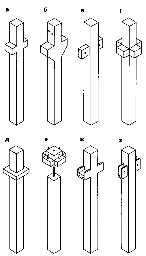
Fig. 12.44. Columns with consoles for supporting the crossbars: a, c - with hidden consoles; b - with trapezoidal consoles; d - with four-sided consoles; d - with a square capital; e - with a console head; w, s - with steel consoles
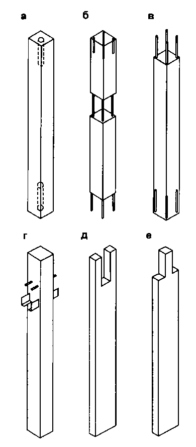
Fig. 12.45. Unconsolidated columns: a - with cylindrical channels above and below; b - with exposed reinforcement in the level of overlap; in - with upper releases of fittings; g - with horizontal reinforcing outlets for connection with crossbars; d - with a forked tip; e - with shoulders for supporting the crossbars
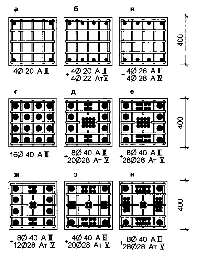
Fig. 12.46. Column reinforcement options. Peripheral reinforcement under load, kN: a - 2000; b - 3000; in - 5000. Mixed reinforcement under load, kN: g - 9000; d - 12000; e - 15000; f - 9000; s - 12000; and - 15000

Fig. 12.49. Joints of columns: a - pin; b - flat with steel base plates; c - with welding of longitudinal reinforcement; g - with welding of steel golovinov; d, e - bolted; g, s - on polymer solutions; 1 - fixing rod; 2 - cement-sand mortar; 3 - mesh indirect reinforcement; 4 - longitudinal reinforcement of the column; 5 - steel plate; 6 - welding; 7 - centering concrete protrusion; 8 - butt niche; 9 - steel ogolovnik; 10 - overlay for welding; 11 - a bolt; 12 - nest; 13 - polymer solution; 14 - hole in the column; 15 - centering gasket
Column trunk reinforcement they are produced with reinforcing bars with a diameter of 12 to 40 mm from steel A-II and A-III (A-IV, A-V), which allows achieving effective gradation of their bearing capacity. Longitudinal and transverse reinforcement (clamps), grids of indirect reinforcement and embedded parts are combined into a single spatial reinforcing cage (Fig. 12.46).
For economic reasons and the conditions for the unification of elements, the bearing capacity of the columns is recommended to be increased by increasing the classes of concrete and reinforcement, and not by increasing the cross-sectional dimensions of the columns.
With considerable effort in the columns and limited (according to unification conditions) sizes of their cross-section, the columns are made with metal cores, which are used as strips (a package of strips), a stacked section made of angle steel - “cabbage”, and also bundles of welded reinforcement (Fig. 12.47).
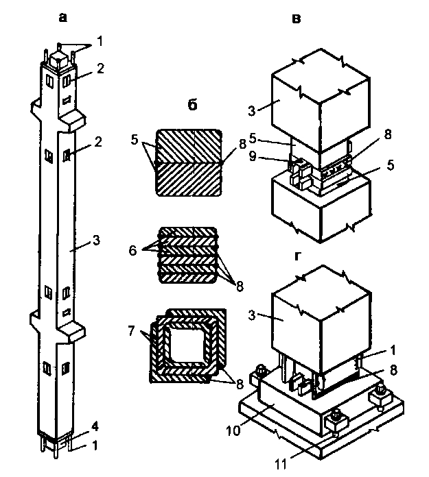
Fig. 12.47. Prefabricated reinforced concrete columns with metal cores: a - general view of the column; b - types of sections of steel cores; in - the joint of the column; g - detail of bearing on the foundation; 1 - releases of reinforcing bars; 2 - steel embedded parts; 3 - column; 4 - steel core; 5 - slabs; 6 - strips up to 60 mm thick; 7 - corners; 8 - weld; 9 - a coupling bolt; 10 - steel base plate; 11 - anchor

Fig. 12.48. Reinforcement of column consoles: a - reinforcement with rigid sheets welded to reinforcement; b - combined type without connection with the longitudinal reinforcement of the columns; 1 - reinforcing frame of the column; 2 - metal console; 3 - steel sheet welded to the longitudinal reinforcement of columns; 4 - combined console design
Column Joints (Fig. 12.49) are divided:
Molded, precast monolithic, with welding of longitudinal reinforcement and without welding;
In shape: flat, spherical, with concrete cutting in the joint zone;
By strengthening the joint zone: metal, metalless.
Supporting columns to the foundation usually carried out through a precast concrete shoe (Fig. 12.50 a). In a node of this type, the transfer of forces occurs through a durable mortar seam, which, being enclosed in a cage, works for collapse.
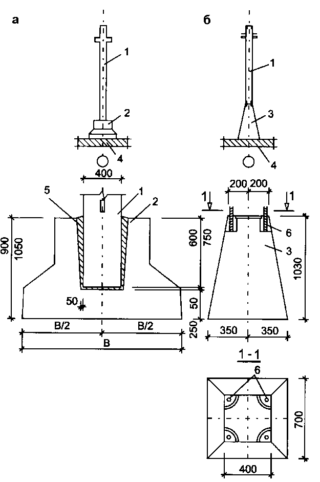
Fig. 12.50. Supporting reinforced concrete columns to the foundation: a - through a glass-type shoe; b - through the pyramidal column; 1 - column; 2 - shoe; 3 - column; 4 - foundation; 5 - concrete; 6 - valve releases
Another type of support (Fig. 12.50 b) using pyramidal-type column columns provides unification of all nodal connections, simplicity of the column-column manufacturing and simpler techniques for achieving the required mounting accuracy.
Reinforced concrete crossbars distinguish between:
By location in the supporting system: ordinary, front, front, stair, staircase;
By the bearing capacity (in kN / m) of the crossbar (for example, 72, 110, 145);
On the span: single-span, two-span, cantilever;
According to the cross-sectional shape: rectangular, T-shaped with a shelf down, T-shaped with a shelf on top, I-shaped, U-shaped, paired, two-branch, etc. (Fig. 12.51 and 12.52);
According to the type of joint with the column: with trimming on the support, with releases of longitudinal reinforcement, with vertical holes, with sockets, etc .;
By the method of production: prestressing with mechanical tension of the reinforcement, with the electrothermal method of tensioning the reinforcement, etc.

Fig. 12.51. Crossbars with support on the console of columns: a - with cutting on a support; b - with trimming and horizontal openings; c - with trimming and nests for supporting minor beams; g - with narrowed supporting ends; d - with trim on the support and shelves for supporting plates; e - with trimming and loop outlets of transverse reinforcement; g - with releases of the upper longitudinal reinforcement; h - the same with the shelves; and - with transverse reinforcement releases; k - with upper sockets and holes for installing bolts; l - an I-section with holes for bolts; m - with sockets for hidden console consoles; n - paired; about - the same, trapezoidal section; p - paired of L-shaped elements; p - two-branch
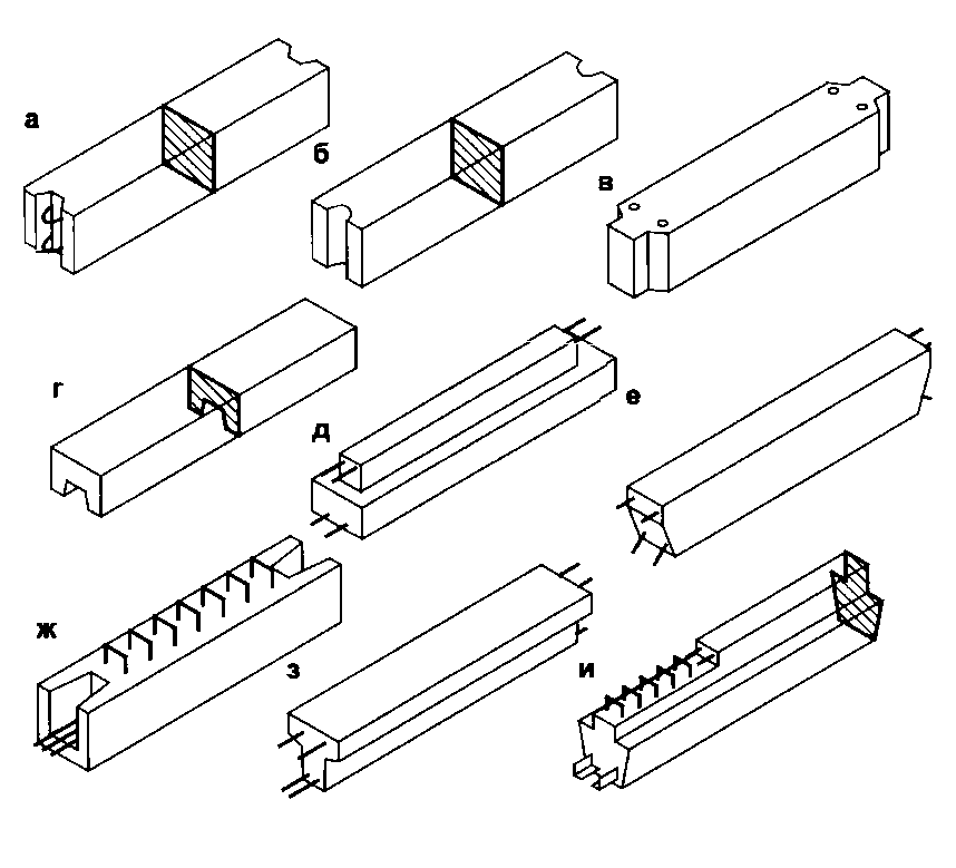
Fig. 12.52. Crossbars of unconsolidated support on columns: a - with loopback releases of longitudinal reinforcement in trapezoidal nests; b - with semi-cylindrical vertical nests; in - with vertical holes; g - U-shaped section; d - with shelves and releases of longitudinal reinforcement; е - with releases of longitudinal reinforcement; g - with the releases of longitudinal reinforcement in the nests and the loopback releases of the transverse reinforcement of the T-section with the releases of the longitudinal reinforcement; and - with releases of longitudinal and transverse reinforcement
Crossbars of frameworks often have a T-shaped cross-section with shelves below for supporting floor slabs on them. This form of the crossbar allows you to reduce the size of the crossbar part protruding into the interior by the thickness of the floor slab, and thereby reduce the height of the floors of the building. The crossbars in the supporting part have clippings corresponding to the size of the console of the columns, as a result of which the crossbar is connected to the column without any consoles or parts protruding into the interior (imitation of the frame unit). The width of the crossbars at the bottom is usually equal to the width of the columns.
Crossbars are made of concrete of classes B25, B30 and B40 and reinforced with spatial frames, which include flat frames, grids and embedded parts, combined by welding.
Stiffness diaphragms in the prefabricated frame system they are formed from prefabricated reinforced concrete elements (the main solution), and are also made of monolithic reinforced concrete in the form of closed stiffness cores (Fig. 12.54 a) and lattice metal structures (Fig. 12.56).
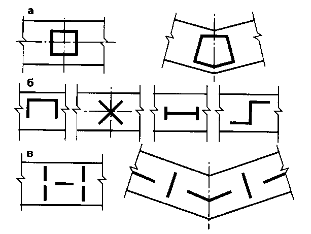
Fig. 12.54. Variants of the formation of stiffness diaphragms: a - closed profiles; b - open; in - flat

Fig. 12.56. Metal bonds of precast unified reinforced concrete frame: a - half-diagonal; b - portal; 1 - prefabricated reinforced concrete columns; 2 - communication; 3 - element for attaching ties to columns; 4 - embedded parts
Prefabricated elements of stiffness diaphragms are divided:
By the type of cross section of the upper part: cantilever (single and double-cantilevered), non-cantilevered;
By type of horizontal joint of diaphragms: with embedded parts in a horizontal seam, with keys, with metal-free contact joint;
By the presence of doorways: openings, unbreakable (deaf), L-shaped (flag).
As a rule, stiffness diaphragms are panels one floor high with a thickness of 140, 160, 180 mm.
Panels of stiffness diaphragms are installed in spans from column to column and expect to work together with them. In the plan, the panels are always installed along the coordination axes, and vertically - so that the seams of the panels coincide with the mark of the top of the floors. The panels are connected to each other and to the columns in the vertical seams in the mounting units by welded joints, which ensure the transmission of vertical shear forces. The transmission of horizontal shear forces is provided by monolithic keyed joints of panels in horizontal joints (Fig. 12.55). All gaps in the joints and junctions of panels to columns and floor slabs are minted with cement mortar and concrete.
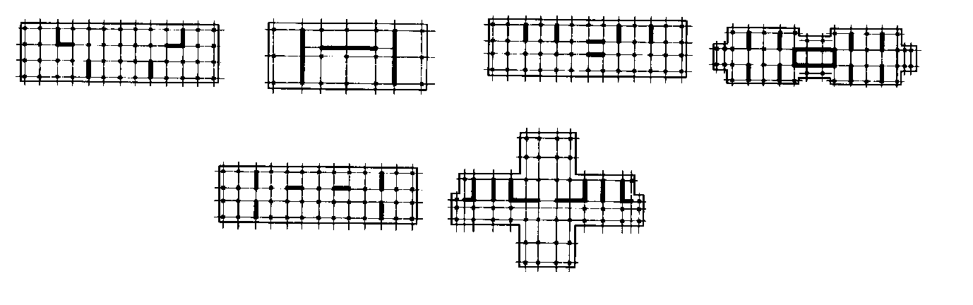
Fig. 12.55. Layout examples of stiffness diaphragms in frame buildings
General sustainability of the building It is ensured by the joint work of horizontal floor disks and vertical stiffness diaphragms. This requires the installation of at least three flat stiffness diaphragms with horizontal axes that do not intersect at one point, i.e. in each temperature block of the building, two diaphragms of one direction and one of the other are needed.
To increase the stiffness of communication systems, it is recommended to combine flat stiffness diaphragms into spatial ones (Fig. 12.54).
The stiffness diaphragms should be distributed evenly over the building plan (Fig. 12.55).
In some cases, for example, with a complex configuration, the stiffness diaphragms are performed in monolithicreinforced concrete. At the same time, if the installation of the main load-bearing structures of the building is ahead of the work on the construction of monolithic diaphragms, then in the places of their installation metal ties are sometimes arranged, which subsequently serve as reinforcement of monolithic diaphragms.
In some cases, and in particular in industrial buildings, in connection with the requirements of the technology, the installation of prefabricated panels is impossible or is associated with losses of a production and functional nature. In these cases, a device is allowed. metal ties (diaphragms of rigidity) half-diagonal or portal type (fig. 12.56).
Crossbars with columns. Depending on the type of frame, purpose, cutting into elements and how to pair them, the joints of the elements perceive various compressive, tensile, bending or shearing forces, separately or in combination with each other.
In prefabricated and precast-monolithic frames, the crossbar can be coupled with the column (Fig. 12.57-12.61) can be hinged or rigidly, welded or bolted, supported on the console of columns or without consoles.
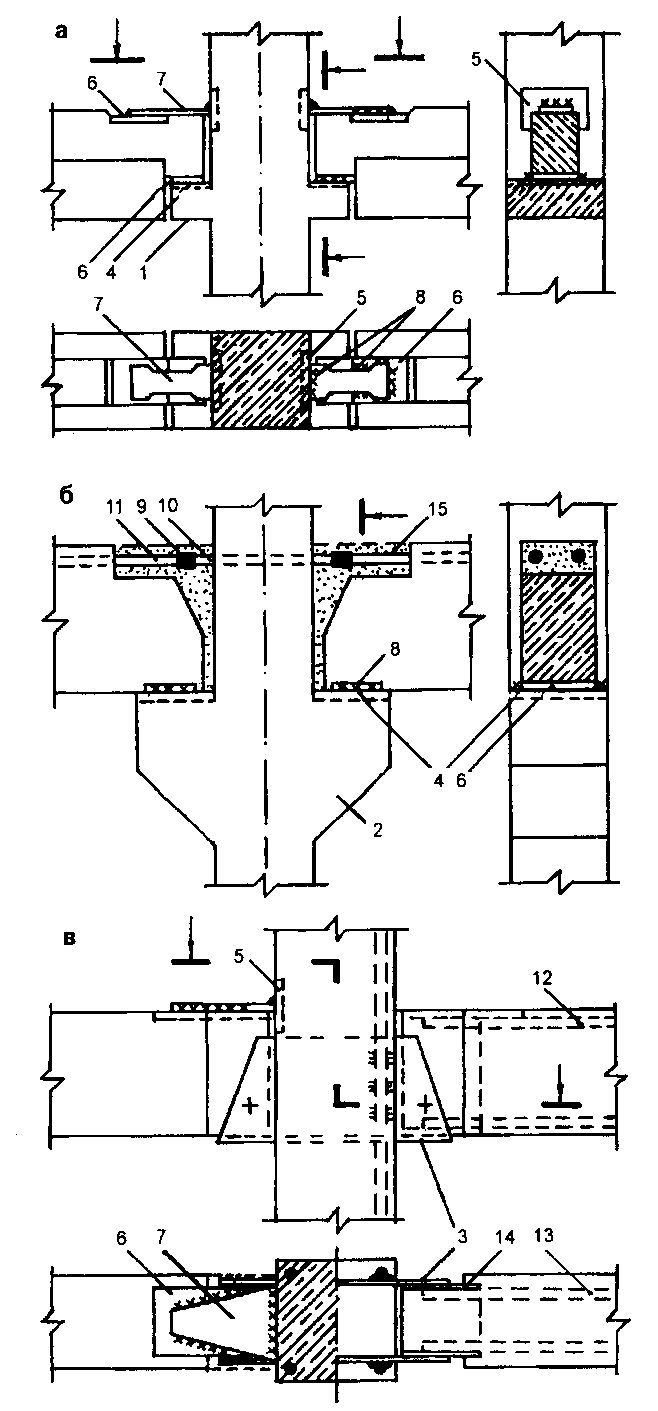
Fig. 12.57. Welded joints of the crossbar with the column: a - articulated with a hidden console; b - hard with an open console; c - the bolt is supported on a steel shoe; 1 - hidden support console of the column; 2 - open console; 3 - steel support shoe; 4 - embedded part of the console of the column; 5 - embedded part of the barrel; 6 - embedded part of the crossbar; 7 - a connecting plate; 8 - welding; 9 - bathroom welding; 10 - release of column reinforcement; 11 - release of reinforcement of the crossbar; 12 - upper reinforcement of the crossbar; 13 - lower reinforcement of the crossbar; 14 - steel clip of the supporting part of the crossbar; 15 - concrete casting
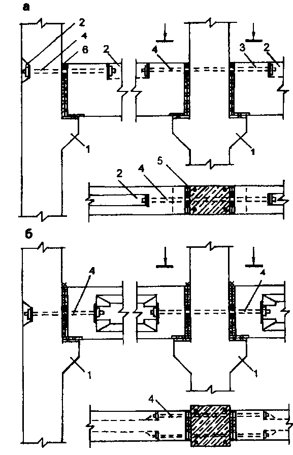
Fig. 12.58. Bolt connections of the crossbar with the column: a - at the level of the top of the crossbar; b - along the axis of the crossbar; 1 - console columns; 2 - nest; 3 - hole (channel); 4 - connecting rods (high strength bolts); 5 - welding of steel sheets; 6 - rubber ring

Fig. 12.59. Pairing the crossbar with the column using the cantilever head:
1 - column; 2 - cantilever head; 3 - crossbar; 4 - reinforcing release of the column; 5 - reinforcing exhaust tip; 6 - floor slab; 7 - cement-sand mortar
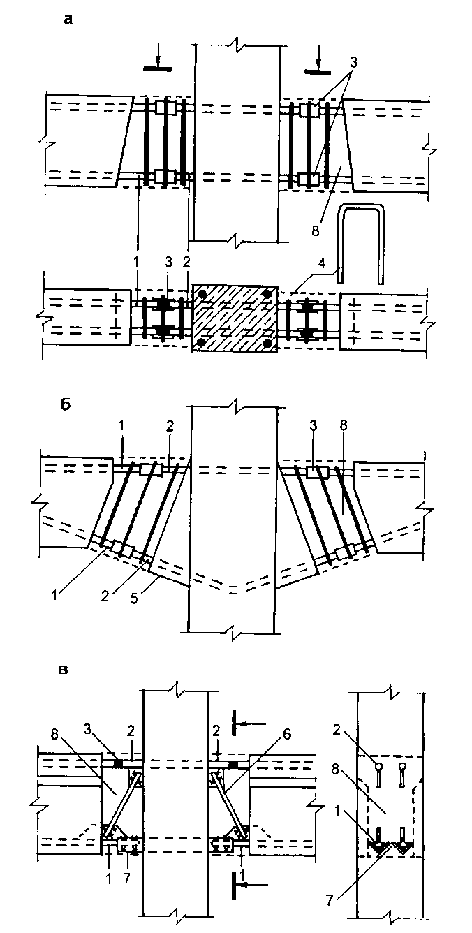
Fig. 12.60. Unconsolidated conjugation of the crossbar with the column with monolithic: a - for normal clamps; b - on inclined clamps; in - with inclined braces; 1 - rebar release of the crossbar; 2 - reinforcing release of the column; 3 - welding the bathroom; 4 - a collar; 5 - vut columns; 6 - brace; 7 - corner release from the column; 8 - concrete casting
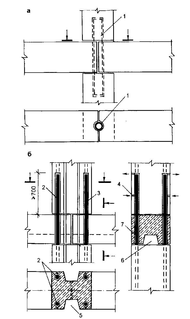
Fig. 12.61. Unconsolidated crossings of the crossbar with the column (platform-plug joints of the columns): a - using a steel tubular rod; b - using reinforcing column outlets; 1 - steel tubular rod; 2 - releases of longitudinal reinforcement of the column; 3 - nest in the lower part of the column; 4 - hole for injection of polymer solution; 5 - a niche for laying vertical communications; 6 - channel for laying horizontal communications; 7 - through hole in the crossbar
Articulation crossbars with columns (for example, Fig. 12.57 a) are used with a bonded frame type. The crossbar is supported by short reinforced concrete or steel consoles protruding from the columns, located under the crossbar or in the crossbars of the crossbar (hidden consoles). Joints are calculated as free-standing beams on consoles.
Widespread hard joints with open reinforced concrete consoles (Fig. 12.57 b). A steel sheet is fastened to the top of the console. Supporting steel sheets are also provided at the ends of the crossbars. When installing the crossbars on the console, these sheets are interconnected by flank seams by electric arc welding. The ends of the upper reinforcement of the crossbars protrude from the concrete and are connected to the horizontal ends of the reinforcement protruding from the column. The connection of the rods is carried out by semi-automatic welding in copper forms with the fusion of the gap between the ends of the reinforcement. The seams between the ends of the beams and columns and the welding zone of the upper reinforcement are filled with concrete. Such a joint is a rigid connection. The prefabricated frame thus becomes a frame structure.
In foreign practice are often used bolted joints crossbars with columns with support of the ends of crossbars on the console of columns (fig. 12.58). Crossbars are connected to each other through a column with connecting rods (middle node) or high-strength bolts (extreme node). Anchor devices for the ends of the crossbars are located in special sockets and are capable of transmitting significant vertical and horizontal loads. If the tie rods are located in the upper part of the crossbar, a sufficiently large bending moment is also transmitted.
Quite often applied consoleless mates crossbars with a column mounted on a construction site with the installation of normal (Fig. 12.60 a) and inclined (Fig. 12.60 b) clamps with monolithic concrete zone at the edge of the column. Welding of rod outlets from the column and crossbars after arranging the clamps is carried out in semi-cylindrical linings. Such conjugation conveys significant horizontal forces and sufficiently large bending moments.
Russian experts have developed a design for the non-cantilever coupling of the crossbar with the column using welded parts in the form of diagonal rods (Fig. 12.60 c). The design, before monolithic, receives considerable rigidity and can absorb the necessary mounting forces without temporary supports.
Wireframe Series Designs 1.020.1-2s / 89 Designed for use in the construction of public and industrial buildings with the following space-planning parameters (Fig. 12.62; Table 12.1):
Floor height: 3,3; 3.6; 4.2; 4.8; 5.4; 6.0; 7.2 m;
The step of the columns in the direction of the crossbars (across the building) and the direction of the floor slabs (along the building): 3.0; 6.0; 7.2; 9.0 m;
Floors: 1-16 floors;
Estimated load on the floor (excluding the dead weight of the plates): from 4 to 21 kN.
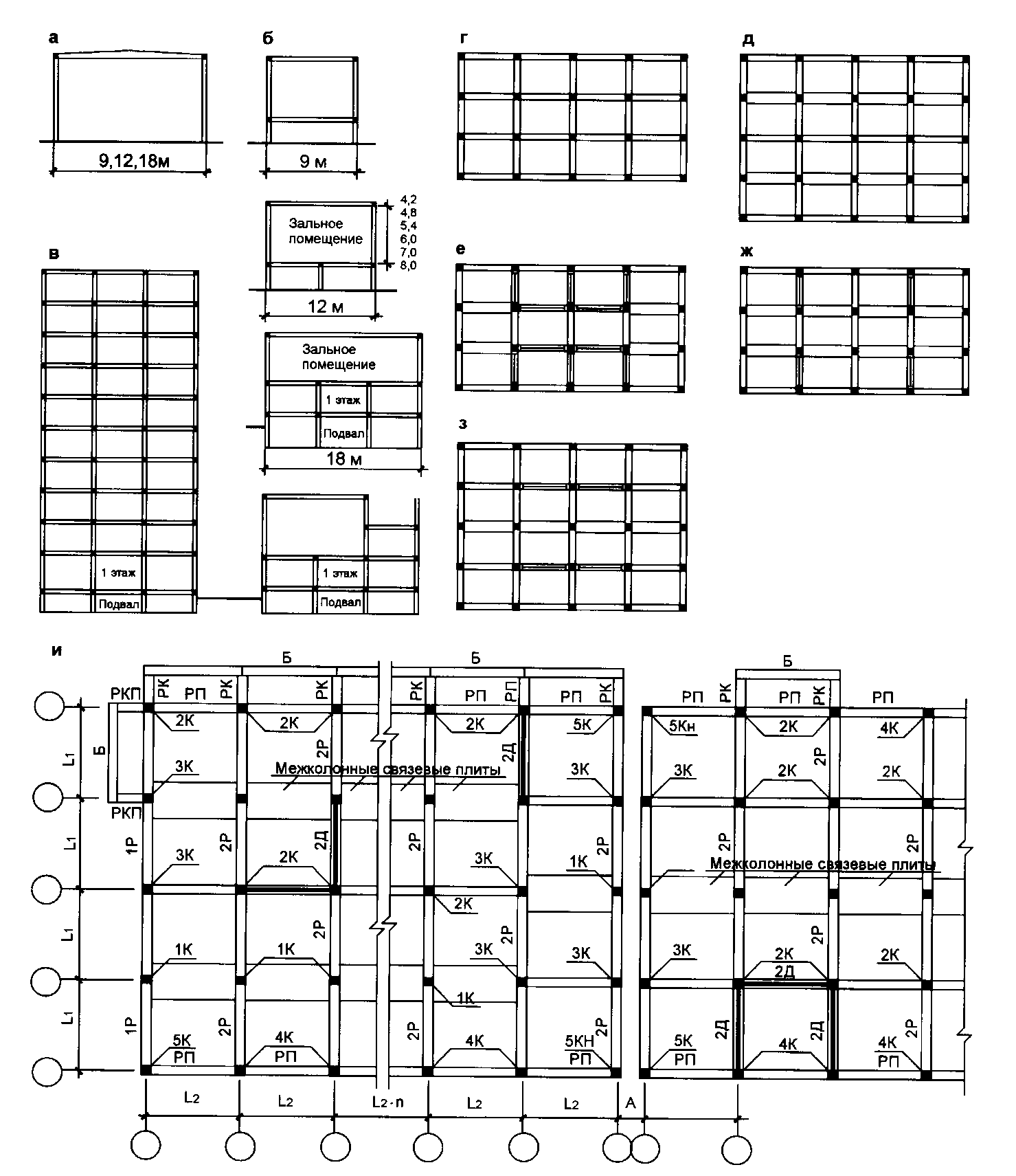
Fig. 12.62. Schemes of frameworks of a series 1.020.1-2s.
Cuts: a - hall; b - two-story buildings; in - a multi-storey building. Structural-static schemes: g - frame in the transverse and longitudinal direction; d - frame in the transverse and incomplete frame in the longitudinal; e - frame-linking; g - frame-link in the transverse direction; h - frame-link in the longitudinal, and - layout plan of the frame elements
Table 12.1. Space-planning parameters of frameworks of a series 1.020.1 -2s / 89

The design of the series provides for the possibility of arranging hall rooms with the arrangement of halls on the second floor of two-story buildings, as well as separate halls (Fig. 12.62 a, b).
The constructions of the series are designed for use in frame and frame-and-link schemes of load-bearing frames of buildings. The following design schemes are applied:
Frame in the transverse and longitudinal directions (Fig. 12.62 g);
The frame diagram in the transverse and incomplete frame in the longitudinal direction (Fig. 12.62 d);
The frame-link scheme with the use of stiffness diaphragms in the transverse and longitudinal directions (Fig. 12.62 e);
Frame-link in one of the directions (Fig. 12.62 g, h);
Possible combinations of the above schemes.
Columns Designed a single section of 400x400 mm for buildings from 1 to 16 floors. At the junctions of the transverse and longitudinal crossbars, the columns are equipped with reinforcement outlets in the upper zone and angular steel consoles in the lower zone of the assembly, designed to be welded to the corresponding outlets from the crossbars in a rigid frame assembly. Corner outlets simultaneously serve as mounting tables for ease of installation of crossbars without the use of mounting devices.
According to the orientation of the columns in the building plan, they are divided into columns (Fig. 12.63), installed:
On the internal and external axes with rigid frame units in the transverse direction (type 1K);
On internal axes with rigid frame units in the transverse and longitudinal directions; along the outer axes at the junction of the cantilever crossbars of balconies (2K);
On the outer transverse axes with rigid frame nodes; along the internal axes of stairwells and expansion joints (3K);
On the outer longitudinal axes with rigid nodes (4K);
In the corners of the building (temperature block) (5K, 5KN).
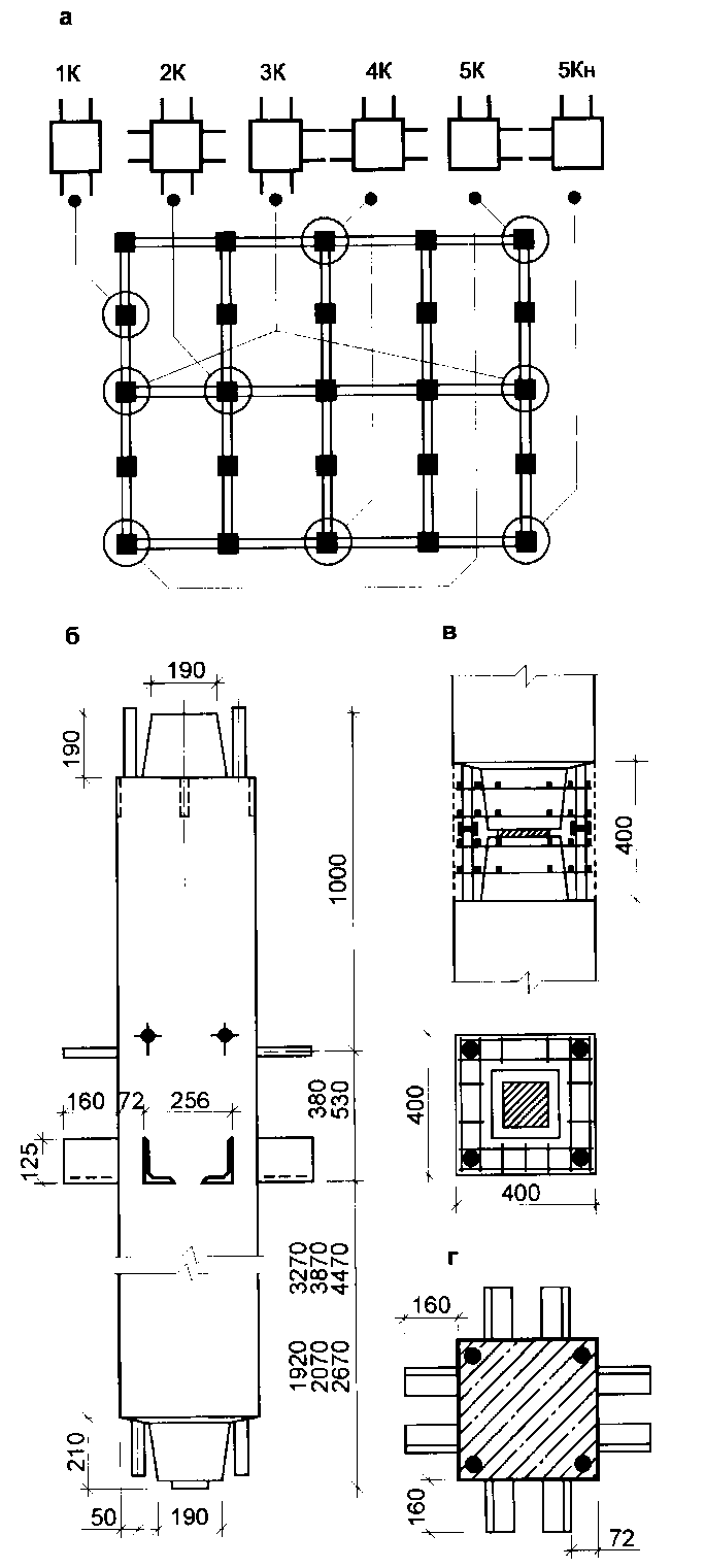
Fig. 12.63. Columns of the frame of the series 1.020.1-2s: a - types of columns in orientation in the plan; b - one-story middle column (type 2KS); in - welded joint of columns; g - section of the column
According to the height of the building, the columns are divided into lower, middle, upper and continuous - for the entire height of the building (from 1 to 3 floors).
The horizontal elements of the frame frames are crossbars transverse and longitudinal directions. Vertical load-bearing crossbars are designed with shelves for supporting floor slabs of two types: multi-hollow slabs with a height of 220 mm and ribbed - 300 mm.
The upper zone of the crossbars is constructed with exposed transverse reinforcement along the entire length of the element or in supporting sections. When mounting in the exposed upper zone, a longitudinal working reinforcement is installed, which is joined with the corresponding releases of reinforcement from the columns in the amount of 2 or 4 pieces in the bathroom welding.
By the nature of the work and the location in the building scheme, the crossbars (Fig. 12.64) are divided into types:
2P - for bilateral support of plates, including flights of stairs;
2PL - for bilateral support of plates, including the staircase beam BL;
1P - end plates for one-sided support of plates, including flights of stairs;
1RL - end for one-sided support of plates and ladder beams BL;
1RP - longitudinal for unilateral support of plates and a flight of stairs;
1RPL - longitudinal for one-sided support of plates and ladder beams BL;
RP - ceilingless, installed along the longitudinal external and internal axes of the building;
1P6.2.26 - for unilateral support of flights of stairs (intermediate platforms) in a span of 3 m;
R6.2.53 - for supporting plates of type P, plates-shells of type KZhS with a span of 18 m and ribbed plates of 3 x 12 m, installed in the coatings of hall rooms;
RK, RCP - cantilever for the installation of balconies with a offset of 1.2 and 1.8 m;
B - bordering beams of balconies;
BL - stair beams for the device of the stairwell in the spans of 7.2 and 9 m.
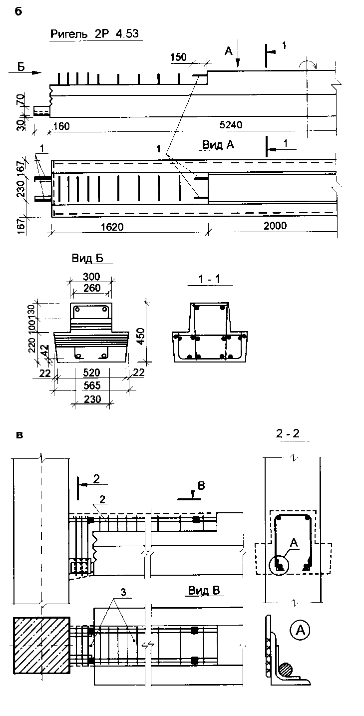
Fig. 12.64. Crossbars of a frame of a series 1.020.1-2s: a - types of crossbars; b - constructive solution of the crossbar 2P 4.53; c - coupling of the crossbar with the column; 1 - releases of longitudinal working reinforcement; 2 - insertion rod for welding; 3 - fine concrete
Stiffness diaphragms (Fig. 12.65) are intended for the construction of buildings with a typical floor height of 3.3; 3.6 and 4.2 m, as well as technical underfloor with a height of 2.0 m. Diaphragm panels are installed in the spans of frames (in axes) of 6.0 and 7.2 m along both transverse and longitudinal axes.
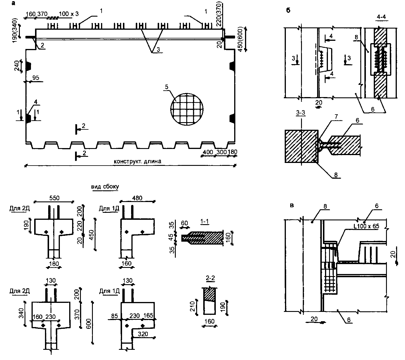
Fig. 12.65. Diaphragms of rigidity of a framework of a series 1.020.1-2s: а - type of diaphragm of rigidity; b - mounting the stiffness diaphragm to the column; c - coupling of stiffness diaphragms in the area adjacent to the column; 1 - releases of vertical reinforcement; 2 - releases of longitudinal reinforcement; 3 - loopback releases; 4 - embedded part for connection with the column; 5 - panel reinforcement; 6 - stiffness diaphragm; 7 - steel rod; 8 - column
The stiffness diaphragms are T- and G-shaped reinforced concrete panels with walls 160 mm thick and shelves 550 and 480 mm wide, respectively. L-shaped panels are installed in stairwells along staircases.
The stiffness diaphragms connected to the columns of the frame and to each other (Fig. 12.65 b, c) form the vertical stiffeners of the frame-frame systems of the frame, which absorb the forces from vertical and horizontal loads. Monolithic foundations for the project are installed under the diaphragms. The diaphragm panels are joined to the foundation, similar to the intersection of diaphragms.
Unified framework of the TK1-2 series (The territorial catalog for construction in Moscow) is intended for the construction of civil and industrial high-rise buildings. The dimensions of the light (Fig. 12.66) and heavy (Fig. 12.67) frames are based on the enlarged module 6M (600 mm) in plan and 3M and 6M vertically. A number of preferred coordination sizes are:
Floor heights: 3.0; 3.3; 4.2; 4.8; 6.0 m;
Spans of crossbars: 1.8-9.0 (after 0.6) and 12.0 m;
Spans of floor slabs: 3.0; 5.4; 6.0; 6.6; 7.2 and
Risalits: 1.2; 1.8; 2.4 and 3.0 m.

Fig. 12.66. The layout scheme of the light frame (according to the TK1-2 series) with cantilever overhangs: КР - ordinary column; KVR - column top ordinary; KK - column under the cantilever crossbar; R - crossbar: RK - console crossbar. Sizes: a - 6000; 9000; b - 1800-9000 through 600; in - 1550; 2150; 2750; g - 2400; 3000; 3300; 3600; 4200; 4800; 6000; 7200; d - 3000; 3300; 3600; 4200; 4800; 6000; e - 3300; 3600; 4200; 6000

Fig. 12.67. The layout scheme of the heavy frame (according to the TK1-2 series) with dimensions: a - 6000; 9000; b - 3000; 6000; 9000; 12000; in - 2750; g - 3300; 3600; 4200; 4800; 6000; 6,600; d - 3000; 3300; 3600; 4200; 4800; 6000; e - 2400; 3000; 3300; 3600; 4200
The layout of the load-bearing reinforced concrete elements of the building is based on a connection scheme, where spatial rigidity is ensured by the joint operation of interconnected vertical (wall-diaphragms) and horizontal (overlap) hard drives. The frame can be arranged with a longitudinal, transverse and combined arrangement of crossbars.
Columns with consoles have a single section of 400x400 mm, their bearing capacity varies with a change in the class of concrete and the percentage of reinforcement, and at high loads - with a transition to rigid reinforcement (from steel profiles). The columns have a one- or two-story cut along the height of the building with the joint located at a height of 0.7 m from the top of the floor slab.
The nomenclature includes columns ordinary, front and loggias. Ordinary columns are installed along the internal axes of the building, have two consoles for supporting the crossbars. Facade columns are placed on the outer axes and have two different consoles (one for supporting the crossbar, the other for the wall slab). Columns of loggias and balconies installed along the front axis can have an external console with an extended overhang of 1.1 or 1.8 m for supporting slabs of balconies or loggias.
Crossbars mainly have a T-section. In accordance with the location in the building plan, the following types of crossbars are distinguished:
Ordinary spans from 3 to 12 m of T-section with a height of 450, 600 and 900 mm;
Facade spans from 1.8 to 9.0 m (after 0.6 m) of a Z-shaped section 690 mm wide and 480 mm high;
Corridor spans from 1.8 to 3.6 m of T-section 300 mm high;
Stair (for supporting staircases) with a span of 6.0; 6.6 and 7.2 m with a corner profile;
Cantilever (for the formation of overhangs) T-sections with a height of 600 and 900 mm.
The crossbars are connected to the column by a node with a hidden reinforced concrete console (see Fig. 12.57a) by welding embedded elements.
The panels of the stiffness walls (diaphragms) are single-story reinforced concrete 180 mm thick, flat with one- or two-sided shelves for supporting floor slabs. The vertical edges of the stiffness diaphragm are connected to the columns or to each other in at least two places along the height of the floor with steel welded joints for embedded parts.
In the practice of building Germany, the most advanced complete prefabricated frame structural system is kVM series of reinforced concrete structures (Fig. 12.68), intended for the construction of mass public, as well as industrial and auxiliary buildings. The frame of the KVM is solved by a coupling scheme with the hinged support of the crossbars on the columns, horizontal stiffness diaphragms from the floor disks and vertical panel stiffness walls or monolithic stiffness cores.

Fig. 12.68. Frame building of the KVM system (Germany): а - the main elements of the building; 6 - single-beam solution of the frame assembly; in - two-beam; 1 - foundation glass type under the column; 2 - tape monolithic foundation under the basement wall; 3 - column; 4 - crossbar; 5 - basement wall panel; 6 - ordinary horizontal panel of the outer wall; 7 - corner element of the wall; 8 - ordinary floor slab; 9 - spacer plate; 10 - wall panel of a vertical section; 11 - landing; 12 - staircase marie); 13 - staircase wall panel
Typical KVM designs allow the layout of the frame with a longitudinal or transverse crossbar. Depending on the load, single or double crossbars are used. In the first case, the crossbar is installed in the nest at the end of the column (Fig. 12.68 b), in the second - two parallel crossbars are supported on the shelves in the side cutouts of the column (Fig. 12.68 c). The grid of columns is from 4.8x4.8 to 7.2x12 m with intermediate values \u200b\u200bthat are multiples of 1.2 m. The height of the floors is from 3.3 to 6 m.
In recent years, Russia has applied frame for residential, public and industrial buildings up to 30 floors in prefabricated option (Fig. 12.69). A feature of this frame is its high forming ability on the orthogonal-diagonal grid of columns with an appropriate arrangement of crossbars. There is the possibility of designing polygonal, triangular, oval, round and other complex shapes of the plan of buildings.
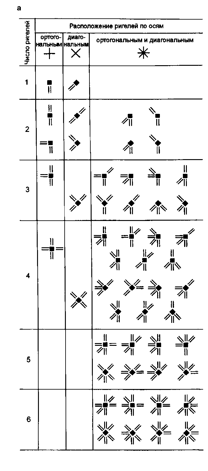
Fig. 12.69. Prefabricated monolithic frames (main nodes):
a - situations of the location of columns and crossbars; b - the pair of crossbars with the column; c - support of reinforced concrete slabs on the crossbar; g - resting precast-monolithic plates on the crossbar; d - conjugation of the stiffness diaphragm with the column; 1 - column, 2 - crossbar; 3 - stiffness diaphragm; 4 - reinforcing releases; 5 - additional fittings; 6 - reinforcing mesh; 7 - monolithic concrete; 8 - mounting (temporary) clamp; 9 - formwork slab; 10 - prefabricated floor slab
Prefabricated frame elements are: columns, girders, stiffness diaphragms, floor slabs. In the monolithic version, the “crossbar-column" unit is originally solved.
Columns with a height of 1-4 floors have square (with a side of 250; 300; 350; 400 and 500 mm) and rectangular sections (from 250x300 to 400 x 600 mm). At the level of the floors, the columns have reinforcement sections free of concrete (bare reinforcement), at the bottom there are releases of longitudinal reinforcement, at the top there are channels for the plug-in joints of the columns in height (Fig. 12.45 b). The height of the floors is 2.8 m (for residential buildings) and 3.3 m (for public and industrial buildings).
Crossbars of rectangular cross section with a width of 300 mm and a height of 200 mm (for prefabricated-monolithic overlapping) or 250 mm (for prefabricated overlapping) have support sockets in which the rods of the lower working fittings from wire ropes of type 7K are released (Fig. 12.52 g). In the upper part of the crossbars there are loop outlets of transverse reinforcement. The length of the crossbars in the axes of the orthogonal grid of columns is from 1.8 m to 6 m (after 0.6), along the diagonal axes - on request up to 6 m.
The coupling of the crossbars with the columns (Fig. 12.69 b) is carried out as follows: the crossbars are supported on the mounting clamps of the columns and are supported by temporary stands; the wire reinforcement of the crossbars is unbent and brought into the free space between the longitudinal reinforcement of the column; two reinforcing bars with ends bent upwards are laid in the nests of the crossbars; two additional reinforcement rods are installed at the top of the outlets of the transverse reinforcement of the crossbars for a length of 1.2-2.4 from the column in two directions; the position of the installed additional reinforcement rods with a diameter of 20-32 mm is fixed by wire binding to reinforcing rods of prefabricated elements; prefabricated floor slabs are supported on the crossbars (Fig. 12.69 c), having recesses in the upper support part, into which the reinforcing bars are laid; all reinforcement outlets and installed rods are concreted.
Overlapping can be performed in a precast-monolithic version (Fig. 12.69 g). For this, formwork slabs with a thickness of 60 mm are used with prestressed wire reinforcement having outlets from the ends of the supporting sides of the slabs. A layer of concrete with a thickness of 100 mm with reinforcing mesh in the upper zone is laid on the plates.
The stiffness diaphragms are paired with the columns by means of looped horizontal outlets of these elements with the installation of vertical connecting rods and monoling the joint with concrete (Fig. 12.69 e).
In Armenia, the original method of building earthquake-resistant residential buildings of increased number of storeys has spread - with spatial precast monolithic frame (Fig. 12.70). The main element of the frame is a rectangular reinforced concrete frame, the dimensions of which correspond to the height of the floor and the pitch of the columns of the building. Usually the length of the frame is 6.1 m, height - 3.0; 3.3; 3.6 m; section - 15x30 cm. The columns of the frame are formed by four pillars of frames; depending on the load on the columns, their cross-section can be increased by expanding the frames. Thus, in accordance with the adopted space-planning decision and design efforts and without changing the size of the prefabricated frames, columns of square or rectangular sections are obtained.
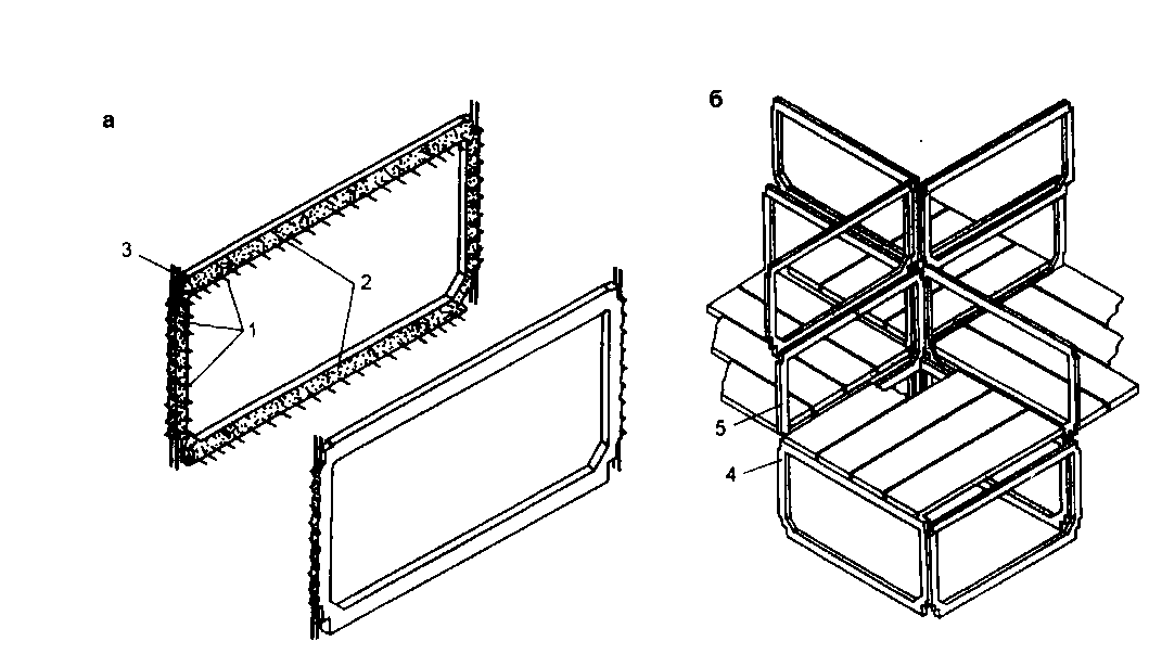
Fig. 12.70. Prefabricated monolithic frame frame: a - prefabricated frame frames; b is a diagram of the formation of the frame; 1 - reinforcing releases; 2 - the surface of the frame facing the cavity monolithic; 3 - longitudinal working rods of racks; 4 - frame of the underlying floor; 5 - frame of the overlying floor
The building frame is assembled from standard products of the same size in the longitudinal and transverse directions. Ceilings are made of standard slabs. The rigidity of the frame is provided by a continuous cross-section of crossbars and columns (their frame design) and monolithic joints. When the building height is increased to 14–20 floors, this frame scheme is converted into a frame-and-link one by installing vertical stiffness diaphragms between the frames (into the grooves of columns and crossbars).
The frame frame is a universal structural system on the basis of which you can create a wide variety of planning and volumetric compositions. A rigid volumetric structure of frames can develop horizontally or vertically, fill the entire space or leave free spaces, easily adapting to the terrain.
If necessary, to ensure free internal space (on all or some floors) and at the same time increase the rigidity of the building, various frames using wall beams or high beams in the form of farms (Fig. 12.71).
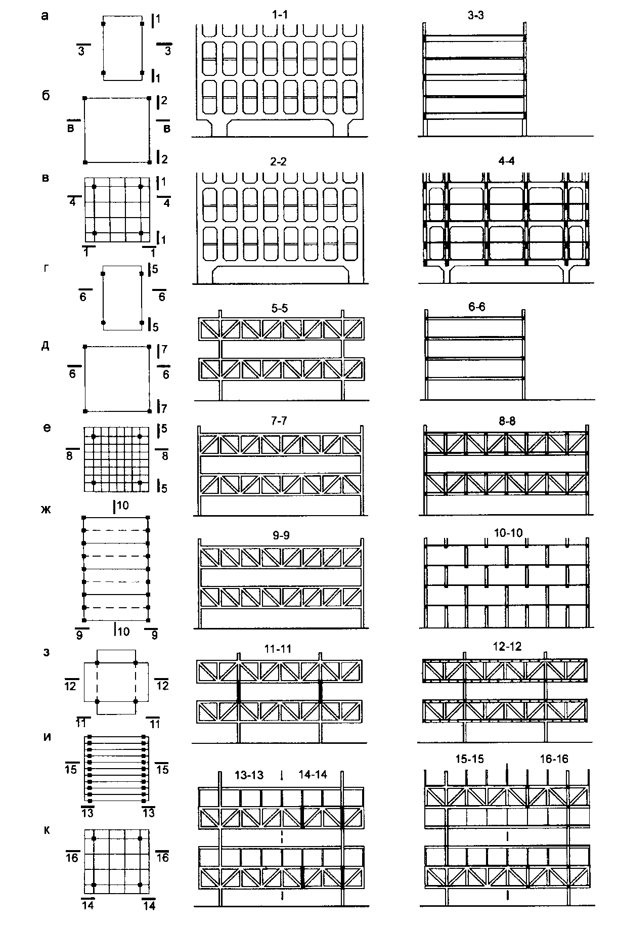
Fig. 12.71. Frameworks with reinforced concrete beam walls and crossbars-trusses:
a-c - structures of external walls in the form of a single beam-wall; GZ - crossbars-farms located across the floor; and, to - crossbar-farms through two or three floors
The entire structure of the external walls can be made as a single beam-wall, supported by columns or portal structures of the first floor. Such beams of the outer walls are parallel to the longitudinal axis of the building (Fig. 12.71 a), along the perimeter of buildings with their shape close to the square (Fig. 12.71 b), or intersect the building in two directions, forming a rigid spatial system (Fig. 12.71 c) .
Crossbars with a height of one floor can be installed so that free space is created in the level of one (across the floor). In this case, they are located along two parallel sides of the building, on all four sides (Fig. 12.71 g, e) or in the form of a spatial lattice (Fig. 12.71 e).
Parallel trusses one floor high can be spaced apart across the width of the building (Fig. 12.71 g) or perpendicular to each other (Fig. 12.71 h).
When the crossbars-farms are located through two or three floors in height, additional ceilings are arranged on racks along the upper belts or suspended from the lower truss belts (Fig. 12.71 and, k).
For some industrial buildings it is advisable to apply frames with inter-farm floors (Fig. 12.72). Large spans of buildings (12, 18, 24 m) are covered with frame-diagonal or bezkrasno reinforced concrete trusses. Within the constructive height of the farms, premises are arranged in which engineering equipment and communications are placed. They also serve as household, warehouse and other auxiliary premises. The height of the inter-farm floors is from 2.4 to 3.6 m, and the production floors are 3.6; 4.8; 6.0 m.

Fig. 12.72. The decision of a multi-storey building with inter-farm technical floors: a - a fragment of a cross section; b - farm-crossbar bezrakosny; c - frame-crossbar truss
Reinforced concrete trusses are crossbars of a multi-story frame, so they are rigidly connected to the columns to form frames in the transverse direction. In the longitudinal direction, the frame is solved according to the connection scheme with the production of vertical metal bonds in each deformation block of the building.
For buildings with inter-farm floors, two types of floor slabs are used. P- or 2T-shaped ribbed slabs are placed on the upper truss belt, since they absorb the load of industrial premises. Multi-hollow or special sanitary-engineering plates with built-in lamps and air distribution ventilation channels rest on the lower farm belt.
Monolithic reinforced concrete frames. The condition for the use of monolithic reinforced concrete for the construction of frame buildings is, first of all, a developed technological base: industrial unified formwork systems; the presence of plastic and workable concrete mixtures; the use of concrete pumps and other equipment for supplying concrete to design elevations.
The advantages of monolithic frames are manifested in the wide possibilities of architectural and structural shaping:
The ability to design a wide variety of structures (Fig. 12.73-12.75);
Variation of the pitch of the columns and the shape of their section;
The device in the buildings of consoles, ledges, sunken sections and other changes in shape;
The use of columns (including inclined ones) and various crossbars, allowing to improve the working conditions of the constructive system and at the same time give the building an architectural expressiveness;
Change the height of floors within the same building.


Fig. 12.73. Monolithic reinforced concrete frames with main and secondary beams: a - types of structural and planning cells; b - layout of elements; in - the shape of the sections of the columns; g - the shape of the main beam crossbars of variable section; d - fragments of sections; 1 - column; 2 - the main beam; 3 - secondary beam; 4 - monolithic floor slab
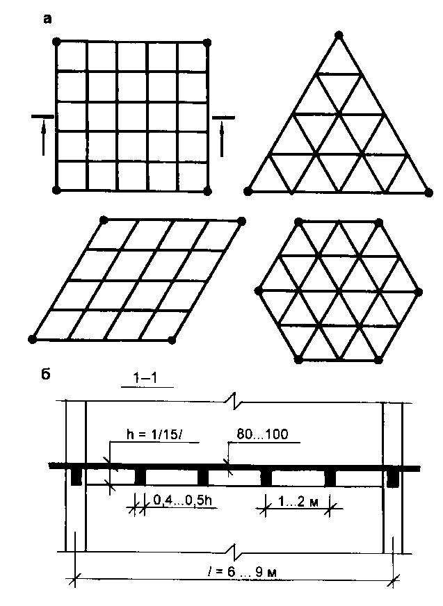
Fig. 12.74. Monolithic reinforced concrete frames with caisson-type ceilings: a - structural and planning cells; b - fragment of the section

Fig. 12.75. Section of the building of the sanatorium with a monolithic reinforced concrete frame
Monolithic frames are designed with frame or frame-coupled (with the device of monolithic stiffness diaphragms).
Depending on the solution of the crossbars (beams), monolithic frame-crossbar systems can be of two types: with main and secondary beams in different directions; with beams of the same value in two or three directions (with ceilings of caisson type).
In the first type of frame, the secondary beams rest on the main beams monolithically connected with them, and those, in turn, are supported on columns (see Fig. 12.73). The layout of the secondary and main beams in plan can be different (with longitudinal or transverse arrangement). When choosing the direction of the main beams, the purpose of the building, the spatial rigidity of the frame, and other requirements are taken into account.
The spans of the main beams are 6-9 (12) m, the cross-sectional height is 1 / 8-1 / 15 of the span, and the width is 0.4-0.5 heights.
In each span of the main beam, one to three secondary beams are located. Secondary beams are also located along the axes of the columns. Their spans are 5-7 m, the cross-sectional height is 1 / 12-1 / 20 of the span, and the width is 0.4-0.5 of the height.
Spans of a monolithic floor slab are equal to the pitch of minor beams and are 2-3 m, and the thickness of the slab, depending on the load, is selected within 1 / 25-1 / 40 of the span and most often is 80-100 mm.
Frames with a frequent arrangement of beams (1-2 m) in two or three directions with the same pitch and height are called frames with coffered ceilings (see Fig. 12.74). Their advantages lie in the relatively lower height of the ceilings (beams) and high architectural expressiveness of the ceilings of public buildings.
Among the promising can be attributed super frame system of shelf type(Fig. 12.76), in which the spatial rigidity of the building is ensured by the so-called superframe, which consists of several box-shaped pylons (trunks) interconnected by powerful grillages at several levels along the height of the building. The grillages (as on shelves of a whatnot) are supported by multistory frames, which can have various planning and design solutions. Shelf-type frames are the most promising for buildings of very large number of storeys (high-rise).
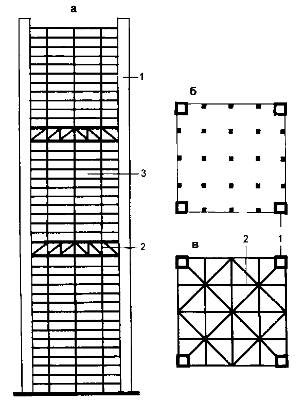
Fig. 12.76. Structural diagram of the rack-type frame: a - facade diagram; b - scheme of a typical floor; in - scheme grillage; 1 - box pylon; 2 - grillage; 3 - frame-bolt structure
In recent decades, technically developed countries have shown an increased interest in prefabricated monolithic frame structuresin which the role of the retained formwork is played by thin-walled reinforced concrete elements. The use of such structures, characterized by a high degree of industrialization, can significantly reduce the complexity and reduce the time of construction of buildings while maintaining all the main advantages of monolithic structures.
In the prefabricated-monolithic version, the main frame elements - columns and beams - are concreted in thin-walled formwork elements of the box section. In the area of \u200b\u200bjoints, the outlets of reinforcement from the formwork elements are monolithic in the process of filling the cavities of columns and beams with concrete mix.
Elements are made of ordinary or prestressed concrete with a wall thickness of 80-120 mm. When using formwork elements made of ordinary concrete, monolithic filling is additionally reinforced.
In order to avoid corrosion of the connecting parts, they are subsequently concreted, coated with anti-corrosion compounds or made of stainless steel.
Columns the framework of one-story industrial buildings can be divided into two groups: used in spans without bridge cranes and in spans with bridge cranes. According to the situation in the building, the columns are divided into extreme (wall) and middle, installed at the junction of two spans.
Prefabricated reinforced concrete type columns. Their weight ranges from 1.8 to 7.9 tons. The height of the columns is taken into account taking into account the possibility of sealing the lower end into the foundation by 900 mm. The columns of the middle rows (with a cross section of 400 X 400 mm) in the upper part have a broadening (head) to support it from two sides of the supporting structures of the coating. With large cross-sectional dimensions of the columns, a head is not made.
Prefabricated reinforced concrete columns for buildings equipped with bridge cranes consist of two parts of a crane and a crane. The crane part serves to support the bearing elements of the coating and is called the column head. The crane section carries the load from the column and from the crane beam along which the bridge cranes move. Depending on the design of the crane part, these columns can be divided into single-branch (cantilever) and two-branch (step). The extreme columns have consoles and ledges on the one hand, the middle columns on both sides.
Typical single-branch columns have a rectangular cross-section and are intended for buildings with a crane rail head located at a height of 6.15, 6.95 and 8.15 m above the floor, with a crane capacity of 10 to 20 g. The weight of the columns is 5 to 9 t
Double-branch columns are used for buildings with a head height of crane rails above the floor level of 8.15, 9.65, 11.45, 12.65 and 14.45 m with a pitch of middle columns of 12 m and a lifting capacity of cranes from 10 to 50 tons. column branches - rectangular. The branches of the crane part are interconnected by horizontal reinforced concrete bonds.
To fix other frame elements, as well as technological and sanitary equipment, special steel parts are laid in the columns during their manufacture.
To verify the position of the columns during installation, risks are applied on their surface - triangular vertical grooves. Risks are done at the upper and lower ends of the column (against the top of the foundation) on all four faces, and, in addition, on the side faces of the consoles.
Communication. Columns and main bearing elements of coatings form a system of transverse frames. To ensure the spatial rigidity of the building between these frames create a system of connections. Connections can be divided into vertical (installed in vertical planes) and horizontal (located in the planes of the upper or lower zones of the truss trusses or beams).
For the stability of the columns in the longitudinal direction and, in particular, for the perception of inertial forces when braking bridge cranes, vertical diagonal connections are made between the columns in the longitudinal rows. These bonds are placed in the middle of each temperature block. They are cross and portal. Portal communications less restrict intra-workshop transport. Between the farms, in the plane of their upper zone, horizontal steel ties are established. Reinforced concrete struts are placed between the nodes of all other farms.
When installing the coating on the runs, in the extreme cells of the temperature blocks over the entire width of the building, steel horizontal ties of the cross system are arranged under the runs.
Reinforced concrete frame of one-story industrial buildings
The frame of a one-story industrial building consists of columns, foundations beneath them, bearing elements of the coating and connections. In addition, the frame includes (if available in the building) - crane, foundation and strapping beams. In the frameworks of buildings of long length, temperature seams are provided that are located no more than 60 m away. These seams are structurally solved by installing double columns. They share the frame of the building.
All prefabricated reinforced concrete frame elements during manufacture are equipped with steel embedded parts for welding or blocking them during installation, as well as mounting loops (or holes) for slinging when lifting structures with cranes.
In order to avoid corrosion of the connecting parts, they are subsequently concreted, coated with anti-corrosion compounds or made of stainless steel.
Foundations for columns. Separate reinforced concrete foundations of the glass type are arranged under the columns of the frame.
Prefabricated reinforced concrete foundations are arranged, as a rule, in the form of a single block, which is a glass with a plate. The weight of such blocks ranges from 1.65 to 4.7 tons.
Under heavy loads, the use of prefabricated foundations, consisting of one block, becomes impractical, due to their heavy weight. In these cases, the foundations are made divided and connected to each other during installation of their individual elements by welding embedded parts or monolithic. The pillars and slabs have vertical holes of a round or oval shape, as a result of which, when the slabs are superimposed, through-holes are formed. To monolith the foundation, the wells of its middle zone are filled with concrete, with the preliminary installation of reinforcing rods or frames in them. In some cases, with the appropriate feasibility study, monolithic step, glass-type foundations are used, performed on site.
Blocks of prefabricated foundations are installed on crushed stone preparation with a thickness of 100 mm; for wet soils, the preparation is made of concrete grade 50.
The upper plane of the foundation, as a rule, is placed 150 mm below the level of the clean floor, which makes it possible to backfill the earth into pits before the installation of the columns. If at the same time, the depth of the foundation sole due to soil conditions (or according to the conditions for deepening the technological equipment) is insufficient, then the foundation is installed on a concrete pad. The height of the foundations, consisting of several rows of elements, can be adjusted by the introduction of additional rows. If you need a very deep foundation, sometimes columns of increased height are used.
To transfer loads from the external and internal walls to the foundations of the columns of the frame foundation beams.
Prefabricated reinforced concrete beams for the pitch of columns 6 and 12 g have a cross-section in the form of a tee. Their height is 400 or 600 mm, and the width on top is 300 or 400 mm. Depending on the length of the beam, there are: basic and shortened (used with a shortened step, for example, near temperature joints).
Under the outer walls, foundation beams are laid with removal beyond the edges of the columns, and under the inner walls they are placed between the columns along the axial lines. When laying, the upper edge of the foundation beams is installed at a level of 30 mm below the floor of the room, which is located 150 mm above the ground surface planned around the building. On top of the foundation beams, waterproofing is made of two layers of rolled material on mastic.
Beams are installed directly on the ledges of the foundations of the columns or on concrete columns resting on these ledges.
Bearing structures of coatings.
Reinforced concrete farms.
Key parameters and dimensions
1. Rafter trusses are divided into types:
· FS - diagonal segment for coatings with a pitched roof;
· FBS - segmentless roofing for coatings with a pitched roof;
· FBM - the same for coatings with a low-slope roof;
· FT - triangular bevelless for pitched roof coatings.
2. Truss trusses are divided into types:
· FPS - for coatings with a pitched roof;
· FPM - for coatings with a steep roof;
· FPN - the same with prestressed truss racks;
· FP - for coatings from slabs with a span length.
Farms with a length of 8960 mm and more are pre-stressed, and 5960 mm long with non-tensioning reinforcement. Trusses with a length of 8960 mm are allowed to be manufactured with non-tensile reinforcement.
Specifications
Farms must meet the requirements of GOST 13015.0:
· In terms of actual concrete strength (transfer, tempering and at design age);
· Frost resistance of concrete, and for farms operating under aggressive gaseous conditions, also water resistance of concrete;
· The average density of lightweight concrete;
· Steel grades for reinforcing and embedded products, including for mounting loops;
· The thickness of the protective layer of concrete to reinforcement;
· Corrosion protection.
Reinforced concrete frame
Frame - reinforced concrete structure, consisting of columns rigidly fixed in the foundations and beams.
A frame is a spatial or rigid rod system in which elements (crossbars, racks) are rigidly connected to each other. Elements can be connected in all or in some nodes. Wooden, reinforced concrete and metal frames serve as load-bearing structures for flyovers, bridges, buildings, and other structures, and they can also be load-bearing elements of installations or machines.
Shell overlap.
Overlap-shell - the building structure of the floors of buildings and structures. In architectural practice, convex, hanging, mesh and membrane shells of reinforced concrete, metals, wood, polymeric, woven and composite materials are used.
Spherical shells may be assembled from flat square plates. The shell of the shell in this case takes the form of a polyhedron with rhombic faces inscribed in a spherical surface. The squares of the plates are complemented to rhombuses due to small changes in the width of the seams.
Plates with diagonal edges 0.2 m high are divided into ordinary, angular and extreme. Corner and extreme plates along the shell contour are equipped with reinforced contour ribs.
On-board elements in the form of segmented trusses consist of an upper belt formed by the contour edges of the plates, a lower belt - tightening from bundles of high-strength reinforcement in a reinforced concrete cage - and braces.
The assembly of the shell is made on steel circles, moved assembled from span to span. When mounting the plates are installed on the mugs in the design position and are interconnected by welding outlets of fittings and monolinging the seams.
Contour ribs are connected by loop joints. The lower part of the truss is assembled at the installation site, brought under the shell and connected to the upper belt by monoling loop outlets in the grooves of the contour ribs.
Side trusses of adjacent shells are combined by a common puff.
Walls of large panels.
In modern construction, the walls of large panels are the most industrial.
Depending on various signs, wall panels are divided into separate types: according to the position in the wall on ordinary, piers, lintels, parapets, cornices and socles; by location in plan - on ordinary and corner; on heat engineering properties - for insulated, used in heated buildings, and insulated for unheated buildings; by cutting - on strip, single and two-module; breed of materials - on reinforced concrete, metal and asbestos-cement.

Fig. 1. A fragment of the facade and a section of the wall from large panels
The most widely used in modern industrial buildings are hinged panels.
Reinforced concrete panels are made both insulated and non-insulated. Insulated panels are used to install the walls of single and multi-story heated frame buildings with a step of wall columns of b and 12 m. These wall panels are made of the following types: solid - from cellular or light concrete, three-layer - from two reinforced concrete plates, with a layer of mineral wool insulation. Continuous panels of cellular concrete are single-layer. The thickness of the panels is 200, 240 and 300 mm. Panels with a thickness of 200 and 240 mm are used only for curtain walls with tape openings, and 300 mm thick for self-supporting walls. Panels made of cellular concrete, like all types of other insulated panels, have a nominal height of 1.2 and 1.8 m.
Fig. 2. Wall panels: a - from cellular concrete; b - from light concrete; c - from heavy concrete (three-layer); g - ribbed reinforced concrete for unheated buildings; d - metal with a heater
Non-insulated panels are used to install the walls of unheated frame industrial buildings with a step of wall columns of 6 and 12 m. The panels are made in the form of ribbed reinforced concrete slabs 6 and 12 m long, 1.2 and 1.8 m high. Panels 6 m long have the same grid of ribs heights -120 mm and a shelf between ribs 30 mm thick. With a width of 1.2 and 1\u003e 8 m, such panels differ in the number of longitudinal ribs.
Panels with a length of 12 m have ribs 300 mm high along the contour and five intermediate transverse ribs of lower height. The panel shelf between the ribs has a thickness of 30 mm. Such panels are made with prestressing longitudinal ribs, and the transverse ribs and the shelf of the panel are reinforced with flat welded frames and nets. Panels 6 m long are completely reinforced with flat welded frames and nets.
Non-insulated panels are used only in curtain walls with tape openings. Reinforced concrete panels with a length of mainly 6 m are also used for the manufacture of three-layer insulated panels. The material for their manufacture, reinforcement, filling the joints between the panels during their installation are basically the same as in the insulated three-layer reinforced concrete panels.
The technology for building reinforced concrete frame houses is rarely used for low-rise buildings. She proved to be most effective in the design and construction of high-rise buildings. At the same time, the reinforced concrete frame of a private house of a small number of storeys will cause a sharp rise in the cost of construction.
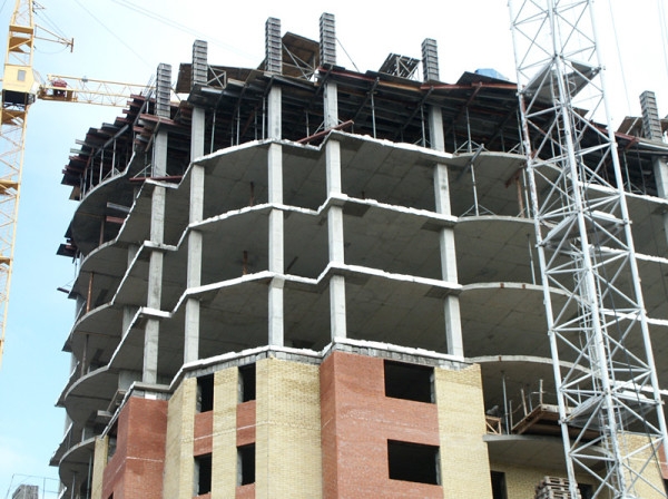
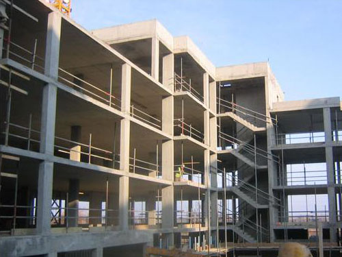
In the photo - reinforced-concrete frame of a multistory building
Reinforced concrete frame has a number of significant advantages:
Tip: if you need to make various passages for communications in the material, use diamond drilling of holes in concrete.

Drilling holes in concrete structures
Reinforced Concrete Composition
He earned the title of the main structural material of our time thanks to the optimal combination of components - reinforcement and reinforced concrete:
The combination of these two components is no coincidence, they complement each other well. Adhering to concrete, reinforcement prevents it from crumbling and breaking during bending or stretching of structures.
The above-mentioned qualities, as well as the resistance of reinforced concrete to the loads that the building is exposed to, allow the material to be used at all stages of construction - from foundations to the roof.
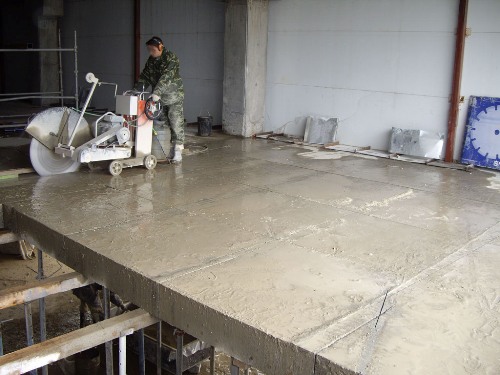
Removing reinforced concrete floors
Varieties of reinforced concrete frames
In the construction industry, there are two types:
They consist of:
- crossbars;
- columns;
- basics of stairways.
Finished elements are delivered to the construction site for subsequent installation. The disadvantage is obvious - the choice of forms is limited due to the standards of parts established by the enterprise.
This type of frame is extremely popular among developers for a number of its advantages:
- there are no restrictions on the configuration and location of the building elements;
- able to take any, even the most incredible architectural forms;
- withstand any number of storeys and load.
For the production of monolithic reinforced concrete frame, together with ceilings, removable formwork is used. The instruction assumes its installation before starting work, the field of which is its pouring with concrete. As a result, the speed of the process increases significantly, which allows you to finish the construction in the shortest possible time.
Reinforced concrete monolithic frame of the building at the construction site
The material of the outer walls does not matter for the frame, they can be:
- brick;
- mounted;
- foam concrete.
Buildings based on the monolith fit perfectly into the architecture and landscape features of the area.
Tip: Owing to the flexibility of designs, apartment owners can afford unusual layout solutions.
Ambient temperature influences the forces arising in structures. To limit this effect, the building is cut into compartments, while the length of the temperature block of the reinforced concrete frame and its other dimensions depend on the material of the frame, the climatic conditions of the region of construction and the thermal regime of the structure. Typically, the parameters are determined by calculation.
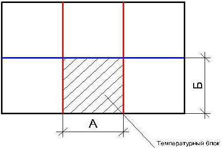
Temperature block
Positive aspects of the monolithic frame
How to build reinforced concrete frame houses
Slight deformation of the reinforced concrete frame occurs due to a failure under the supporting column. It arises from the interaction of a monolithic frame with a foundation plate. The failure is foreseen by the project in order to reduce the cost of materials during the construction of the building.
But most of all, a solid reinforced concrete frame is valued for its resistance to technological disasters. The rigid base will withstand a powerful explosion, resulting in the destruction of the outer walls.
Multistory housing based on it is offered in all price categories - from budget to luxury. Practice has proved that the consumer properties of a multi-story building of this type are much higher compared to the panel and brick versions.
Improving the effectiveness of monolithic frame housing
Despite the high technological parameters and safety qualities, builders are in constant search for improving the properties of monolithic frames, the effectiveness of their use and reducing the cost of materials. One of these methods is to increase the grade of concrete used. Due to this, the consumption of expensive steel reinforcement is reduced and construction estimates are reduced.
The greatest efficiency is achieved when reinforcing concrete by 3% or more.
The monolithic frame is optimized for:
- section of elements from reinforced concrete;
- brand;
- the degree of reinforcement of the concrete used.
Another method also used in monolithic frame construction is to deepen the building's box into the ground to a depth of two floors. The underground and basement parts, including the outer walls, are made in a monolithic version. Thus, the rigidity of the building is increased due to the transfer of loads from the building to a more dense structure of reservoir soils.

Construction of a monolithic frame private house
Unfortunately, the cost of building a low-rise family house using this technology is still inaccessible to most citizens. Significant cost items are expensive formwork systems and rental equipment for the delivery of concrete mix and concrete production.
For such purposes, the use of prefabricated structures, which are much cheaper. And the load on the building with a height of 2-3 floors is much lower and the use of a monolithic frame in this case becomes irrational due to the low efficiency of its use.
From the article it became clear that frame construction is characterized by two types - prefabricated reinforced concrete frame and monolithic. They differ from each other in the way of installation at the construction site - the first is made at the factory and assembled at the facility, the second - directly at the work site.
The use of reinforced concrete frame makes it possible to create reliable buildings of free planning. The video in this article will help you find additional information on this topic.