Automation of individual heating points (ITP). Individual heating point Functional diagram, etc.
The control system for an individual heating station (ITP) is designed to distribute the coolant to adjacent subsystems: ventilation, heating system, hot water supply, booster pump system.
The ITP control cabinet informs about the current state of the system by means of light indication. The operator panel provides display on video frames of the current information about the state of the actuators (valves and pumps), the operating modes of the equipment, and also gives information about the current pressures and temperatures of the subsystems. In addition, the visualization panel provides the ability to switch the actuators to manual control mode.
On the front side of the control cabinet there is an operator panel, consisting of eleven video frames, which are designed to monitor the status and control of the ITP system.
Composition and functionality of video frames:
This project provides for:
- local control of pressure and temperature of cold and hot water in heating and hot water systems;
- automatic regulation of the water temperature for heating depending on the outside temperature;
- automatic regulation of water temperature in the DHW system;
- automatic control of pumps in the heating system;
- automatic control of circulation pumps in the DHW system;
- installation of a freely programmable controller PLC160-220.u-M from Aries and a monochrome graphic control panel IP320, while the controller works in conjunction with input modules from OWEN;
- the choice "work - reserve" is carried out according to the specified programs of the total operating time of the equipment and optimization of start and stop;
- installation of Danfoss control valves.
The controller with I / O modules and control panel is installed in the control panel.
Alarms:
- pressure drop in the pressure pipes of the pumps;
- excess of hot water temperature for heating;
- excess of hot water temperature at DHW;
- lowering the temperature of hot water for heating;
- lowering the temperature of hot water for DHW; are collected on the board in a common light signal;
- "Crash". The "Emergency" signal is reset by the button on the IP320 panel.
The controller is programmed in the CoDeSys environment in accordance with the IEC 61131 standard. Programming languages \u200b\u200bare supported, including the graphical functional programming language.
The commissioning works include verification, calibration of equipment, functional testing of programs and equipment, and commissioning of the system.
The technical solutions adopted in the working drawings comply with the requirements of environmental, sanitary and hygienic, fire safety and other standards in force on the territory Russian Federation, and ensure safe operation of the facility for human life and health, subject to the measures specified in the working drawings.
The set of working documents was made on the basis of the technical task and in accordance with the requirements of the current rules and regulations:
- SP41-101-95: Designing of heat points;
- GOST 21.408-93: Rules for the implementation of working documentation for the automation of technological processes;
- RM 106-82: Electrical schematic diagrams of automation systems. Implementation requirements;
- GOST R50571: Electrical installations of buildings. Basic provisions. Security requirements.
On the basis of OWEN automation equipment, the specialists of the "Control Devices and Drive" company have developed an automated control system for individual heating units in a residential complex in Perm. The hot and cold water supply to the four 25-storey high-rise buildings is controlled by devices such as PLC, I / O modules, operator panels.
Features of ITP automation
Individual heating units are complex technological objects with many monitored and measured parameters, as well as various control loops. They must be constantly monitored, and it is difficult to keep track of everything with the help of one service personnel, without appropriate automation. Indeed, the operator often responds to an emergency with a great delay. As a result, the scale of the accident can be very significant, and it is very difficult to understand its causes in such cases. All this damages the business, turns into unjustifiably large material costs for the service organization. For example, an excess of pressure can lead to a rupture of the pipeline, an excess of temperature - to an increase in the cost of heat carriers, a pump failure in winter - to freezing of the pipeline.
Only the creation of an automated control system makes it possible to ensure the safe operation of equipment at individual heating points, makes it possible to quickly identify emergency and pre-emergency situations, promises economic benefits due to a significant reduction in maintenance costs and the use of labor resources.
Let's list the main goals of creating an automated control system:
Prompt and reliable receipt of information about the object in real time;
Monitoring the condition of technological equipment;
Prompt identification of emergency and pre-emergency situations;
The ability to control all technological parameters of objects from the control room due to remote dispatching.
At the same time, a number of rather stringent requirements are imposed on the system being created. ACS should:
Work around the clock in real time in accordance with the operating mode of technological equipment;
Be scalable, that is, if necessary, allow to connect additional parameters and objects;
Be simple and convenient for production personnel;
Have opportunities for development and modernization.
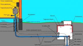
As an example, consider an automated system of individual heating points, which was developed and implemented by specialists of the company "Pribory Control and Drive" in one of the residential complexes of the city of Perm. The residential complex consists of four 25-storey buildings and two individual heating points - one ITP for two houses. The block diagram of the system is shown in Fig. 1.

Fig. 1. ITP ACS block diagram
The following parameters are monitored in each individual heating point:
DHW and cold water temperature and pressure in the supply and return pipelines;
Water temperature and pressure in the lower and upper heating zones;
Voltage presence;
Status of circulation, feed and fire pumps (on / off / emergency);
Cold water pump control.
Choice of automation tools
Today's market for software and hardware automation is so vast and rich that in most cases it is quite difficult to choose the optimal equipment required. But, as always, the main issue is the ratio of price and quality. And in this regard, the products of the Russian manufacturer look the most attractive, because the prices for Russian products are much lower than for foreign ones. has been in the automation market for over twenty years and has established itself as a supplier of reliable and high-tech products that are used in a wide variety of distribution systems - from the simplest to the most complex. It is also important that the company has its representative offices, service and engineering centers in all regions of Russia, where it is possible at any time, either by phone or in person, to receive comprehensive advice on installation, programming and commissioning of equipment.
Therefore, the ITP automated control system was based mainly on the OWEN automation tools, namely: a programmable logic controller, input / output modules, operator panels, power supplies. Among the equipment of other manufacturers we can name a GSM modem - Siemens mc35i, pressure sensors SDV.
The software was developed using the MasterScada SCADA system. The video frame of the main mnemonic diagram is shown in Fig. 2. The SCADA-system implements signaling of deviations of parameters from the norm with recording in the archive log of messages, archiving system parameters with the ability to view trends for each measuring channel, control of technological equipment.

Fig. 2.AWP of the operator. ITP mnemonic diagram
The second ITP has an operator panel manufactured by OWEN. The panel implements the same functions as at the operator's automated workstation: monitoring of technological parameters, control of cold water pumps, viewing trends in technological parameters, keeping a log of alarms.
Setting up an automatic system
In 2011, the automated system of the first individual heating unit was launched, as a result of which there was no need for the constant presence of service personnel. All information about accidents or system deviations is delivered to the service organization via SMS and calls. In addition, you can control technological parameters using SMS requests or remotely from another workplace. For example, if it is required to start or stop pumps, the operator turns them on or off using SMS or from the operator's workstation. Now it is possible to archive technological parameters, analyze data and operate equipment.
The experience of successful work on the implementation of the automated control system allowed at the beginning of 2012 to carry out its expansion, namely to connect a second ITP. Since the system has the ability to modernize and expand, the connection of the second individual heating point was completed quickly and efficiently.
Individual is a whole complex of devices located in a separate room, which includes elements of thermal equipment. It provides connection to the heating network of these installations, their transformation, control of heat consumption modes, operability, distribution by types of heat carrier consumption and regulation of its parameters.
Individual heating point
A heating installation, which either deals with its individual parts, is an individual heating unit, or abbreviated ITP. It is designed to provide hot water supply, ventilation and heat to residential buildings, housing and communal services, as well as industrial complexes.
For its operation, you will need to connect to the water and heat system, as well as the power supply necessary to activate the circulation pumping equipment.
A small individual heating station can be used in a single-family house or a small building connected directly to a centralized heating network. Such equipment is designed for space heating and water heating.
A large individual heating station is engaged in the maintenance of large or multi-apartment buildings. Its power ranges from 50 kW to 2 MW.
Main goals
An individual heating station provides the following tasks:
- Accounting for heat and coolant consumption.
- Protection of the heat supply system from an emergency increase in the parameters of the coolant.
- Shutdown of the heat consumption system.
- Uniform distribution of the heat carrier throughout the heat consumption system.
- Regulation and control of the parameters of the circulating fluid.
- coolant.
Benefits
- High efficiency.
- Long-term operation of an individual heating point has shown that modern equipment of this type, unlike other non-automated processes, consumes 30% less
- Operating costs are reduced by about 40-60%.
- Selecting the optimal heat consumption mode and precise adjustment will reduce heat energy losses by up to 15%.
- Silent work.
- Compactness.
- The overall dimensions of modern heating points are directly related to the heat load. With a compact arrangement, an individual heating station with a load of up to 2 Gcal / hour occupies an area of \u200b\u200b25-30 m 2.
- Possibility of placing this device in small basements (both in existing and newly constructed buildings).
- The work process is fully automated.
- The maintenance of this heating equipment does not require highly qualified personnel.
- ITP (individual heating station) provides comfort in the room and guarantees effective energy saving.
- The ability to set the mode, focusing on the time of day, the use of the weekend and holiday mode, as well as weather compensation.
- Individual production depending on customer requirements.

Heat energy metering
The basis of energy saving measures is the metering device. This accounting is required to perform calculations for the amount of consumed heat energy between the heat supply company and the subscriber. Indeed, very often the estimated consumption is much higher than the actual one due to the fact that when calculating the load, heat suppliers overestimate their values, referring to additional costs. Installation of metering devices will help to avoid such situations.
Purpose of metering devices
- Ensuring fair financial settlements between consumers and suppliers of energy resources.
- Documenting the parameters of the heating system, such as pressure, temperature and flow rate.
- Control over the rational use of the power system.
- Control over the hydraulic and thermal operation of the heat consumption and heat supply system.
Classic metering device scheme
- Thermal energy meter.
- Pressure gauge.
- Thermometer.
- Thermal converter in the return and supply pipelines.
- Primary flow transducer.
- Mesh magnetic filter.
Service
- Connecting a reading device and then taking readings.
- Analysis of errors and finding out the reasons for their occurrence.
- Checking the integrity of the seals.
- Analysis of the results.
- Verification of technological indicators, as well as comparison of thermometer readings on the supply and return pipelines.
- Topping up oil in sleeves, cleaning filters, checking grounding contacts.
- Removal of dirt and dust.
- Recommendations for the correct operation of internal heat supply networks.
Heat point diagram
The classic ITP scheme includes the following nodes:
- Heating network input.
- Metering device.
- Ventilation system connection.
- Heating system connection.
- Hot water connection.
- Coordination of pressures between heat consumption and heat supply systems.
- Make-up of independently connected heating and ventilation systems.

When developing a project of a heat point, the mandatory nodes are:
- Metering device.
- Pressure matching.
- Heating network input.
Completion with other units, as well as their number is selected depending on the design solution.
Consumption systems
The standard scheme of an individual heating point may have the following systems for providing heat energy to consumers:
- Heating.
- Hot water supply.
- Heating and hot water supply.
- Heating and ventilation.
ITP for heating
ITP (individual heating point) - an independent scheme, with the installation of a plate heat exchanger, which is designed for 100% load. The installation of a double pump is provided to compensate for the pressure loss. Make-up of the heating system is provided from the return pipeline of heating networks.
This heat point can be additionally equipped with a hot water supply unit, a metering device, as well as other necessary blocks and assemblies.

IHP for DHW
ITP (individual heating point) is an independent, parallel and single-stage scheme. The set includes two plate-type heat exchangers, each of them is designed for 50% load. There is also a group of pumps designed to compensate for the decrease in pressure.
Additionally, the heating point can be equipped with a heating system block, a metering device and other necessary blocks and assemblies.
ITP for heating and hot water supply
In this case, the work of an individual heating unit (ITP) is organized according to an independent scheme. A plate heat exchanger is provided for the heating system, which is designed for 100% load. The hot water supply scheme is independent, two-stage, with two plate-type heat exchangers. In order to compensate for the decrease in the pressure level, the installation of a group of pumps is provided.
The heating system is replenished with the help of appropriate pumping equipment from the return pipe of heating networks. Make-up of hot water supply is carried out from the cold water supply system.
In addition, the ITP (individual heating station) is equipped with a metering device.

ITP for heating, hot water supply and ventilation
The heating installation is connected according to an independent scheme. The heating and ventilation system uses a plate heat exchanger designed for 100% load. The hot water supply scheme is independent, parallel, single-stage, with two plate heat exchangers, each designed for 50% load. The pressure drop is compensated by means of a pump group.
The heating system is replenished from the return pipe of heating networks. Make-up of hot water supply is performed from the cold water supply system.
Additionally, an individual heating point can be equipped with a meter.
Principle of operation
The scheme of the heat point directly depends on the characteristics of the source supplying energy to the ITP, as well as on the characteristics of the consumers it serves. The most common for this thermal installation is a closed hot water supply system with an independent heating system connection.

An individual heating station has the following operating principle:
- Through the supply pipeline, the coolant enters the ITP, gives off heat to the heaters of the heating and hot water supply system, and also enters the ventilation system.
- Then the coolant is sent to the return pipeline and is fed back through the main network for reuse to the heat generating enterprise.
- A certain volume of the coolant can be consumed by consumers. To replenish the losses at the heat source in CHP and boiler houses, make-up systems are provided, which use the water treatment systems of these enterprises as a heat source.
- The tap water entering the heating plant flows through the pumping equipment of the cold water supply system. Then some of its volume is delivered to consumers, another is heated in the first stage hot water heater, after which it is sent to the hot water circulation circuit.
- Water in the circulation loop by means of circulation pumping equipment for hot water supply moves in a circle from the heating point to consumers and back. In this case, as needed, consumers take water from the circuit.
- In the process of circulation of the liquid along the circuit, it gradually gives off its own heat. To maintain the coolant temperature at an optimal level, it is regularly heated in the second stage of the hot water supply heater.
- The heating system is also a closed loop, along which the coolant moves with the help of circulation pumps from the heating point to consumers and back.
- During operation, coolant leaks from the heating system circuit may occur. Replenishment of losses is handled by the ITP make-up system, which uses primary heating networks as a heat source.
Permit to use
To prepare an individual heating station in a house for admission into operation, the following list of documents must be submitted to Energonadzor:
- The current technical conditions for connection and a certificate of their fulfillment from the power supply organization.
- Design documentation with all necessary approvals.
- The act of responsibility of the parties for the operation and separation of the balance sheet, drawn up by the consumer and representatives of the energy supplying organization.
- The act of readiness for permanent or temporary operation of the subscriber branch of the heating point.
- ITP passport with a brief description of heat supply systems.
- Help on the readiness of the heat metering device.
- Certificate on the conclusion of an agreement with an energy supplying organization for heat supply.
- The act of acceptance of the work performed (indicating the license number and the date of its issue) between the consumer and the installation organization.
- persons for the safe operation and good condition of heating installations and heating networks.
- List of operative and operative-repair persons responsible for the maintenance of heating networks and heating installations.
- A copy of the welder's certificate.
- Certificates for used electrodes and pipelines.
- Acts for hidden works, an executive diagram of a heat point with an indication of the numbering of valves, as well as a diagram of pipelines and valves.
- Act for flushing and pressure testing of systems (heating networks, heating system and hot water supply system).
- Official and safety precautions.
- Operating Instructions.
- Certificate of admission to operation of networks and installations.
- The register of instrumentation, the issuance of work orders, operational, accounting for defects identified during the inspection of installations and networks, knowledge testing, as well as briefings.
- Heat supply outfit for connection.

Safety measures and operation
The personnel serving the heating point must have the appropriate qualifications, and the responsible persons should be familiarized with the operating rules, which are stipulated in This is a mandatory principle of an individual heating point approved for operation.
It is forbidden to start up the pumping equipment with the shut-off valves at the inlet closed and in the absence of water in the system.
During operation it is necessary:
- Monitor the pressure readings on the pressure gauges installed on the supply and return pipelines.
- Observe the absence of extraneous noise, and also avoid excessive vibration.
- Monitor the heating of the electric motor.
Do not use excessive force when manually operating the valve, and do not disassemble the regulators if there is pressure in the system.
Before starting the substation, it is necessary to flush the heat consumption system and pipelines.
Individual heating point - is a set of devices, consisting of elements of thermal power plants, pipelines, shut-off and control valves, circulation pumps, heat exchangers, equipment and automation devices that connect heat consumers in a building (heating and hot water supply systems) to a district or city heat network and transfer heat to them energy. ITP is located in a separate room or annex.
The main purpose of the ITP is to transfer heat from the supplier to the consumer's network, and the main task of the ITP automation system is to provide the consumer with the required amount of heat with the highest possible efficiency and with minimal losses - comfort and efficiency.
With the help of ITP automation, the following tasks are solved:

Typical ITP scheme
ITP systems dissolve the heat suitable for the building into several circuits (two or more) - it can be several circuits of heating, ventilation, underfloor heating and a hot water supply circuit, which differs from the others in that it is possible to take a coolant from it.
The circuits intended for heating are usually closed, all the coolant circulating in them, passing through the heating devices, is returned, from the DHW circuit it is possible to draw hot water by consumers, unused water is returned to the heating station, where it is mixed with cold water from the water supply to make up for losses and warmed up.

Water heating in the circuits is carried out in heat exchangers from the heat of the network or boiler. From this circuit, when the pressure drops in the heating circuit, they are replenished with water. To ensure the movement of water along the DHW and heating circuits, circulation pumps are used, and they also supply cold water to the DHW circuit.
The control of the flow rate of the coolant is carried out using valves with an electric actuator or using frequency converters, which in many cases is more economical.
Basic elements of ITP automation
The automation equipment of individual heating units is similar to the automation equipment of other climate control systems (heating or ventilation), it is carried out using the following elements:


ITP Automation Approaches
When solving a problem heat point automation, it is necessary to take into account the following features of the ITP operation: adjusting and maintaining the temperature, flow rate or pressure drop of the coolant depending on the time of the year, day, and taking into account weekends and holidays, as well as logging and data transfer to the central control panel, etc.
These tasks can be performed taking into account consumption within the facility (more expensive during construction, but cheaper during operation) or with “conditional” accounting.
Local automation. It assumes a “conditional” accounting of the system operation parameters. As a rule, such systems are delivered complete with equipment (complete automation panels) and have a certain number of user settings. Developing your own control algorithm is not available to the user. Take into account the work of external systems according to the parameters at the "input" of flows in the ITP.

Automation based on heat consumers works as part of a building automation and control system. In such systems, the project provides for individual automation panels based on freely programmable controllers. The user has the opportunity to develop their own control algorithm, which will take into account such parameters as the presence of people in the premises or the current (instant) water consumption in the DHW circuits. It all depends on the task of the customer. Obviously, the development and cost of individual shields is higher than the cost of complete shields.

Which automation shield is preferred? It is logical to assume that everything depends on the scale of the system and the absolute value of the savings figure. Obviously, for a small facility, absolute savings on utilities will never pay back the costs of developing individual automation, for a large industrial facility, such a shield can pay off within six months.
Economic effect of implementation
The economic effect of the introduction of ITP automation is achieved due to the following factors (we are talking about automation, taking into account the work of consumers):

- Reducing heat energy losses by reducing the area and temperature of the outer surface of the heat exchangers.
- Reducing heat energy losses by increasing the heat transfer coefficient of heat exchangers, reducing the required temperature head and heat carrier flow for heating water;
- Reducing the energy consumption for transferring the coolant due to the optimal circulation of hot water provided by the use of efficient circulation pumps and software control of the pumps and the temperature of the hot water.
- Reducing the consumption of thermal energy in the heating system due to the introduction of an effective automatic system for the facade control of fuel cell consumption by outside temperature.
ITP Automation System Design
The cycle of works on ITP automation begins with obtaining the technical conditions of the heat supplier and the development of tasks for the design of ITP. Possibilities of placement, power and operating conditions are taken into account. Much attention in the design of ITP is given to the choice of automation equipment. A rational approach at this stage provides significant cost savings while maintaining the operational qualities of the ITP. The working documentation of the ITP automation project may contain the following sections:

Coordination of the project with the facility’s operation service will allow for the provision of possible modes of operation and the elimination of future emergencies. In addition, this will allow the commissioning and commissioning of the future ITP.

Often, the ITP automation project is carried out as part of a separate set of drawings related only to the heating unit, and may contain sections of the power supply and lighting of the ITP, heat mechanics and automation.
Implementation and Maintenance Costs
Long-term operation of individual heat points in Russia and in the world has shown that the use of modern equipment and the development of effective control algorithms can reduce the heat energy consumption of an object by 30% or more. The costs of operating and repairing equipment can be reduced by 40-60%. Detection of heat leaks and timely informing the operating service reduces heat loss by up to 15%.
S. Deyneko
Individual heat point (ITP) - a set of devices consisting of elements that ensure the connection of a heating system and hot water supply to a centralized heat network. The main elements of the ITP are: heat exchangers, pumps, valves, sensors, controllers, various control units and shut-off and control valves
At the same time as ITP, heat metering units are installed in buildings, which allow tracking the amount of heat actually consumed by the building for heating, hot water supply or ventilation. This makes it possible for the consumer to make settlements with the heat supply organization according to meter readings, which, in turn, encourages the rational use of energy resources by modernizing their systems. You will find more detailed information on the installation of heat metering units in the article “Correct installation of a heat meter in an apartment building”.
ITP is the most important component of building heat supply. The regulation of heating and hot water, as well as the efficiency of the use of thermal energy, largely depend on its characteristics. Therefore, ITP pays great attention to the thermal modernization of buildings, and at the moment large-scale projects for their arrangement in apartment buildings are being implemented in various regions of Ukraine.
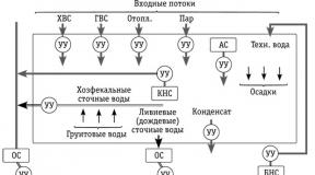
In connection with the mass installation of ITP, the distribution of thermal energy from the heat source to the consumer also changes (Fig. 1).
Fig. 1. Schemes for the distribution of thermal energy from a heat source to a consumer
Modern solutions allow you to connect each building directly to a heat source, bypassing the central heating points (DHC). This scheme makes it possible in the event of an accident or pipeline repair to disconnect only one consumer from the system, and not the entire group, while depriving many consumers of heating or hot water.
The temperature schedule of the heat network determines what mode the individual heat point will operate in the future and what equipment needs to be installed in it. There are several temperature graphs of the network:
- 150/70 ° C;
- 130/70 ° C;
- 110/70 ° C;
- 95 (90) / 70 ° C.
If the temperature of the coolant does not exceed 95 ° C, then it remains only to distribute it throughout the heating system. In this case, it is possible to use only a collector with balancing valves for hydraulic linking of the circulation rings. If the temperature of the coolant exceeds 95 ° C, it cannot be used directly in the heating system without temperature adjustment. It is in this that the important function of the heat point lies. In this case, it is necessary that the temperature of the coolant change depending on the temperature of the outdoor air.
In the heat points of the old sample (Fig. 2, 3), an elevator unit was used as a regulating device. This made it possible to significantly reduce the cost of equipment, however, with the help of such a TP it was impossible to accurately control the temperature of the coolant, especially during transient operation of the system, i.e. when the outdoor temperature ranged from +5 to minus 5 ° C. The elevator unit provided only “quality” adjustment, when the temperature in the heating system changed depending on the temperature of the coolant coming from the centralized heating network. This led to the fact that the "adjustment" of air temperature in the premises was carried out by consumers using an open window and with huge heat costs, going nowhere.
 Fig. 2. Scheme of a heat point with an elevator unit:
1 - supply pipeline; 2 - return pipe; 3 - latches; 4 - water meter; 5 - mud collectors; 6 - manometers; 7 - thermometers; 8 - elevator; 9 - heating appliances
Therefore, the minimum initial investment resulted in financial losses in the long term. Particularly low efficiency of the elevator units was manifested with increasing energy prices, as well as the inability to operate a centralized heating network according to the temperature or hydraulic schedule for which the previously installed elevator units were designed.
 Fig. 3. Thermal input into the building and elevator unit of the "Soviet" era
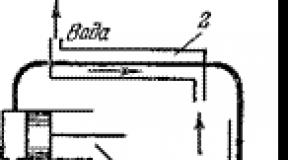
The principle of operation of the elevator is to mix the coolant from the centralized network and water from the return pipe of the heating system to a temperature corresponding to the normative for this system. This is due to the principle of ejection when using a nozzle of a certain diameter in the design of the elevator (Fig. 4). After the elevator unit, the mixed coolant is supplied to the heating system of the building. The elevator combines two devices at the same time: a circulation pump and a mixing device. The efficiency of mixing and circulation in the heating system is not affected by fluctuations in the thermal regime in heating networks. All adjustment consists in the correct selection of the diameter of the nozzle, throttle washer and ensuring the necessary mixing ratio (standard ratio 2.2). For the operation of the elevator unit, there was no need to supply electric current.
 Fig. 4. Schematic diagram of the design of the elevator unit
However, there are numerous disadvantages that negate all the simplicity and unpretentiousness of the maintenance of this device. The operational efficiency is directly affected by fluctuations in the hydraulic mode in the heating networks. So, for normal mixing, the pressure drop in the supply and return pipelines must be maintained within 0.8 - 2 bar; the temperature at the outlet of the elevator is not adjustable and directly depends only on the temperature change of the external network. In this case, if the temperature of the coolant coming from the boiler room does not correspond to the temperature schedule, then the temperature at the outlet of the elevator will be lower than necessary, which will directly affect the internal air temperature in the building.
Such devices have been widely used in many types of buildings connected to a centralized heating network. However, at present they do not meet the requirements for energy conservation, and therefore must be replaced by modern individual heating units. Their cost is much higher and power supply is required for work. But, at the same time, these devices are more economical - they can reduce energy consumption by 30 - 50%, which, given the increase in energy prices, will reduce the payback period to 5 - 7 years, and the life of the ITP directly depends on the quality of the controls used, materials and the level of training of technical personnel in its maintenance.
Modern ITP
Energy saving is achieved, in particular, by regulating the temperature of the coolant, taking into account the correction for changes in outdoor temperature. For these purposes, a set of equipment is used in each ITP (Fig. 5) to ensure the necessary circulation in the heating system (circulation pumps) and temperature control of the coolant (control valves with electric actuators, controllers with temperature sensors).
 Fig. 5. Schematic diagram of an individual heat point using a controller, a control valve and a circulation pump
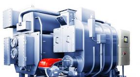
Most individual heating units also include a heat exchanger for connecting to an internal hot water supply system (DHW) with or without a circulation pump, depending on the DHW circuit. A set of equipment depends on specific tasks and source data. That is why, due to various possible design options, as well as its compactness and transportability, modern ITPs are called modular (Fig. 6).
 Fig. 6. Modern modular individual heating unit assembly
Consider the use of ITP in dependent and independent schemes for connecting heating to a centralized heating network (DHC).
In an ITP with a dependent connection of the heating system to external networks, the circulation of the coolant in the heating circuit is supported by a circulation pump. The pump is controlled automatically from the controller or from the corresponding control unit. The controller also automatically maintains the required temperature graph in the heating circuit. This is done by acting on the control valve located on the supply pipe on the side of the external heating network (“hot water”). A mixing jumper with a non-return valve is installed between the supply and return pipelines, due to which the coolant is mixed into the supply pipe from the return line of the heating system, with lower temperature parameters (Fig. 7).
 Fig. 7. Schematic diagram of a modular heat point connected in a dependent circuit
In this scheme, the operation of the heating system depends on the pressures in the central heating network. Therefore, in many cases, it will be necessary to install differential pressure regulators, and, if necessary, pressure regulators "after themselves" or "up to yourself" on the supply or return pipelines.
In an independent system, a heat exchanger is used to connect to an external heat source (Fig. 8). The circulation of the coolant in the heating system is carried out by a circulation pump. The pump is controlled automatically by the controller or the corresponding control unit. Automatic maintenance of the required temperature graph in the heated circuit is also carried out by an electronic controller (controller). The controller acts on an adjustable valve located on the supply pipe on the side of the external heating network (“hot water”).
 Fig. 8. Schematic diagram of a modular heat point connected in an independent circuit:
1 - controller; 2 - two-way control valve with electric actuator; 3 - heat carrier temperature sensors; 4 - outdoor temperature sensor; 5 - pressure switch to protect the pumps from dry running; 6 - filters; 7 - latches; 8 - thermometers; 9 - manometers; 10 - circulation pumps for heating; 11 - check valve; 12 - control unit for circulation pumps; 13 - heat exchanger
The advantage of this scheme is that the heating circuit is independent of the hydraulic modes of the centralized network. Also, the heating system does not suffer from a mismatch in the quality of the incoming coolant coming from the external network (the presence of corrosion products, dirt, sand, etc.), as well as pressure drops in it. At the same time, the cost of capital investments when using an independent scheme is greater - due to the need for installation and subsequent maintenance of the heat exchanger.
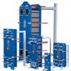
As a rule, modern systems use collapsible plate heat exchangers (Fig. 9), which are quite easy to maintain and maintain: in case of loss of tightness or failure of one section, the heat exchanger can be disassembled and the section replaced. Also, if necessary, you can increase power by increasing the number of plates of the heat exchanger. In addition, independent systems can use soldered, non-separable heat exchangers.
 Fig. 9. Collapsible heat exchangers for independent heating and domestic hot water
According to DBN V.2.5-39: 2008 “Engineering equipment of buildings and structures. External networks and facilities. Heating networks ”, in general, the connection of heating systems according to a dependent scheme is prescribed. An independent scheme is prescribed for residential buildings with 12 or more floors and other consumers, if this is due to the hydraulic mode of the system or technical specifications of the customer.
DHW from an individual heating station
The simplest and most common is a circuit with a single-stage parallel connection of hot water heaters (Fig. 10). They are connected to the same heating network as the heating systems of buildings. Water from the external water supply network is supplied to the domestic hot water heater. In it, it is heated by network water coming from a heat source.
 Fig. 10. Scheme with dependent connection of the heating system to an external network and one-stage parallel connection of the DHW heat exchanger
Chilled mains water returns to the heat source. After the hot water heater, the heated tap water enters the domestic hot water system. If the devices in this system are closed (for example, at night), then the hot water through the circulation pipe is again supplied to the DHW heat exchanger.
In addition, a two-stage DHW heating system is used. In it, in winter, cold tap water is first heated in the first-stage heat exchanger (from 5 to 30 ° C) with a coolant from the return pipe of the heating system, and then water is used to finally warm the water to the required temperature (60 ° C) from the supply pipe of the external network . The idea is to use the waste heat of the return line from the heating system for heating. At the same time, the consumption of network water for heating water in a hot water supply is reduced. In the summer, heating occurs according to a single-stage scheme.
 Fig. 11. Scheme of an individual heating unit with independent connection of the heating system to the heating network and parallel connection of the DHW system
For multi-story high-rise (more than 20 floors) housing construction, schemes with independent connection of the heating system to the heating network and parallel connection of the hot water supply are mainly used (Fig. 11). This solution allows you to divide the heating and domestic hot water systems of the building into several independent hydraulic zones, when one ITP is in the basement and provides the lower part of the building, for example, from the 1st to the 12th floor, and on the technical floor of the building there is exactly the same heat point for 13 - 24 floors. In this case, heating and domestic hot water are more easily regulated in case of a change in the heat load, and also have less inertia in terms of hydraulic mode and balancing.
Alternative to ITP Regulation
Over the past few years, combined valves combining a differential pressure controller and a control valve in one casing have begun to use combined valves to control the flow of coolant in the ITP.
Functionally, it is possible to imagine a combined valve as a pairing of three functional elements (Fig. 12): an automatic differential pressure control valve (V2), a control valve (V1), and a measuring diaphragm (V3).
 Fig. 12. Schematic diagram of the device of the combined valve
The automatic differential pressure regulator-valve (V2) is equipped with an integrated diaphragm module, by means of which a predetermined differential pressure P1-P2 is maintained in the section between the built-in measuring diaphragm of variable section (V3) and the control valve (V1). Thus, restriction and maintenance at a predetermined level of coolant flow through the valve is carried out. To automatically control the valve bore (V1), an electric drive is installed on it.
 Fig. 13 a. Scheme with dependent connection of the heating system to an external network using a combination valve
Flow and temperature controllers are successfully used in circuits with dependent (Fig. 13 a, 13 b) and independent connection of consumers to heating networks, replacing two separate devices - differential pressure regulator and electric control valve.
 Fig. 13 b Scheme with dependent connection of the heating system to an external network using a combination valve
In the case of its application in the ITP, the combined valve is located instead of the differential pressure regulator and the electric control valve.
ITP Hardware Requirements
According to current standards, equipment, fittings, monitoring, control and automation devices should be placed in the ITP, with which they carry out:
- regulation of the temperature of the coolant according to weather conditions;
- change and control of coolant parameters;
- accounting of thermal loads, heat carrier and condensate costs;
- heat carrier cost control;
- protection of the local system from an emergency increase in the parameters of the coolant;
- post-treatment of the coolant;
- filling and replenishment of heating systems;
- combined heat supply using thermal energy from alternative sources.
Consumers should be connected to an external network according to schemes with minimal water consumption, as well as saving heat energy by installing automatic heat flow controllers and limiting the cost of network water. It is not allowed to connect the heating system to the heating network through the elevator together with an automatic heat flow controller.
It is prescribed to use highly efficient heat exchangers with high heat engineering and operational characteristics and small dimensions. At the highest points of the TP pipelines, air vents should be installed, and it is recommended to use automatic devices with non-return valves. At the lowest points, fittings with shut-off valves for draining water and condensate should be installed.
A dirt collector should be installed at the inlet to an individual heat point on the supply pipe, and strainers should be installed in front of pumps, heat exchangers, control valves and water meters. In addition, the mud filter must be installed on the return line in front of the control devices and metering devices. Pressure gauges should be provided on either side of the filters.
To protect the DHW channels from scale, the norms prescribed the use of magnetic and ultrasonic water treatment devices. Forced ventilation, which must be equipped with ITPs, is designed for short-term operation and should provide a 10-fold exchange with an unorganized influx of fresh air through the front doors.
In order to avoid exceeding the noise level, ITP is not allowed to be located nearby, under or above the premises of residential apartments, bedrooms and kindergarten games rooms, etc. In addition, it is regulated that the installed pumps must be with an acceptable low noise level.
An individual heating unit should be equipped with automation means, devices for heat engineering control, metering and regulation, which are installed on site or on the control panel.
ITP automation should provide:
- regulation of thermal energy costs in the heating system and limiting the maximum consumption of network water at the consumer;
- set temperature in the domestic hot water system;
- maintaining static pressure in heat consumer systems with their independent connection;
- set pressure in the return pipe or the necessary pressure drop of water in the supply and return pipelines of heating networks;
- protection of heating systems from high pressure and temperature;
- turning on the backup pump when the main worker is turned off;
- the ability to integrate ITP work into a single regulatory and monitoring system (SCADA).
Modern individual heating points allow you to use remote access to control the heat point. This allows you to organize a centralized dispatch system and monitor the operation of heating and domestic hot water. Suppliers of equipment for ITP are leading manufacturers of relevant equipment, for example: automation - Honeywell (USA); pumps - Grundfos (Denmark), Wilo (Germany); heat exchangers - Alfa Laval (Sweden), Tranter (Sweden), etc.
It is also worth noting that modern ITPs include quite sophisticated equipment that requires periodic technical and service maintenance, which consists, for example, in washing mesh filters (at least 4 times a year), cleaning heat exchangers (at least once every 5 years), and so on. .d. In the absence of proper maintenance, the equipment of the heating station may become unusable or malfunction.
At the same time, there are pitfalls in the design of all ITP equipment. The fact is that in domestic conditions the temperature in the supply pipe of a centralized network often does not correspond to the standardized one indicated by the heat supply organization in the technical conditions issued for the design.
In this case, the difference in official and real data can be quite significant (for example, in reality, a coolant with a temperature of not more than 100 ° C is supplied instead of the indicated 150 ° C, or a non-uniformity of the temperature of the coolant from external networks is observed over the time of day), which accordingly affects the choice of equipment, its subsequent work efficiency and, as a result, its cost. For this reason, it is recommended that during the reconstruction of the ITP at the design stage, measurements of the real parameters of heat supply at the facility and take them into account in the future when calculating and choosing equipment. At the same time, due to possible inconsistency of the parameters, the equipment should be designed with a margin of 5-20%.
Implementation in practice of an individual heating unit for an apartment building
The first modern energy-efficient modular ITPs in Ukraine were installed in Kiev in the period 2001 - 2005. within the framework of the World Bank project “Energy Saving in Administrative and Public Buildings”. In total, 1,173 ITPs were installed and put into operation.
Video. Implemented project using an individual heating unit in an apartment building, saving up to 30% on heating
Modernization of the heating station is one of the conditions for increasing the energy efficiency of the building as a whole. Currently, a number of Ukrainian banks are engaged in lending for the implementation of these projects, including in the framework of state programs. You can read more about this in the previous issue of our magazine in the article “Thermo-modernization: what exactly and for what means”.
At the moment, more than a dozen major projects to install ITP have been implemented in many cities of Ukraine with the involvement of various sources of financing. The installation and use of individual heating units leads not only to increase the efficiency of the use of thermal energy, but also to its significant savings, which in modern realities makes our country more independent from other energy supplying countries.
Read articles and news in the Telegram channelAW-Therm. Subscribe to YouTube channel.
Viewed: 206,742