Motor control and protection circuit. Connection diagrams for three-phase electric motors. Electrical installation technology
Typical control schemes for electric drives with HELL
AMs with a squirrel-cage rotor of low and medium power are started by direct connection to the network without limiting the starting currents. Control circuits of AM with a phase rotor of medium and high power should provide for the limitation of currents during their start-up, reverse and braking using additional resistors in the rotor circuit.
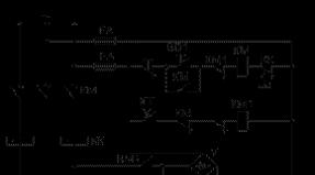
The reversible control circuit of AM with a squirrel-cage rotor is shown in Figure 8.9.
Fig. 8.9. Reversible BP control schemesquirrel cage rotor
The main element this circuit is a reversing magnetic starter, which includes two line contactors KM1 and KM2 and two thermal protection relays KK. The circuit provides direct start and reversal of the motor, as well as anti-rotation braking during manual (non-automatic) control.
The circuit provides protection against motor overloads (relay KK) and short circuits in the stator circuit (circuit breaker QF) and control (FA fuses). In addition, the control circuit also provides zero protection against the disappearance (decrease) of the mains voltage (contactors KM1 and KM2).
Starting the engine when the QF circuit breaker is on, in the conditional "Forward" or "Backward" directions, press the SB1 or SB2 buttons, respectively. This leads to the operation of the contactor KM1 or KM2, the connection of the motor to the network and its run.
For reversing or braking of the motor, the SB3 button is first pressed, which leads to the disconnection of the contactor still on (for example, KM1), after which the SB2 button is pressed. This leads to the switching on of the KM2 contactor and the supply of the power supply voltage to the IM with a different phase sequence. The magnetic field of the engine changes the direction of rotation to the opposite one, and the reverse process begins, which consists of two stages: braking by opposition and takeoff in the opposite direction.
Whenneed only braking when the motor reaches zero speed, the SB3 button must be pressed again, which will disconnect the motor from the network and return the circuit to its original position. If the SB3 button is not pressed, it will cause the engine to run in the other direction, i.e. to its reverse.
To avoid short circuit in the stator circuit, which can occur as a result of the simultaneous erroneous pressing of the SB1 and SB2 buttons, a special mechanical interlock is sometimes provided in reversing magnetic starters. It is a lever system that prevents one contactor from being pulled in when the other is on. In addition to mechanical interlocking, the circuit uses the typical electrical interlocking found in reversing control circuits. It provides for the cross connection of the break contacts of the KM1 apparatus into the coil circuit of the KM2 apparatus and vice versa.
Note that the use of an air circuit breaker QF in the circuit contributes to an increase in reliability and ease of operation. Its presence excludes the possibility of the drive operation in the event of a single phase breakage, with a single-phase short circuit, as can occur when installing fuses, and it also does not require replacement of elements (as in fuses when their fuse-link burns out).
The AM control circuit providing direct start and dynamic braking as a function of time is shown in Fig. 8.10.

Fig. 8.10. The scheme of starting and dynamic braking of blood pressure
Starting the engine is carried out by pressing the SB1 button, after which the KM line contactor is activated, which connects the motor to the power source. At the same time, closing the KM contact in the KT time relay circuit will cause it to operate and close its contact in the KM1 braking contactor circuit. However, the latter does not work, since before that the opening contact of the KM opened in this circuit.
To stop the engine the SB3 button is pressed, the KM contactor is disconnected, opening its contacts in the motor stator circuit and thereby disconnecting it from the network alternating current... At the same time, the KM contact is closed in the KM1 apparatus circuit and the KM contact in the KT relay circuit is opened. This leads to the inclusion of the braking contactor KM1, feeding into the stator winding direct current from the rectifier V through the resistor RT and transferring the motor to the dynamic braking mode.
The KT time relay, having lost power, begins to count the time delay. After a time interval corresponding to the engine stop time, the KT relay opens its contact in the KM1 contactor circuit, which turns off, stopping the DC supply to the stator circuit. The circuit returns to its original position.
The intensity of dynamic braking is regulated by the resistor RT, with the help of which the required constant current in the motor stator is set.
To exclude the possibility of simultaneous connection of the stator to alternating and direct current sources, a typical blocking is used in the circuit using break contacts KM and KM1, connected crosswise in the coil circuit of these devices.
The control scheme for starting and braking by opposing an IM with a phase rotor as an EMF function is shown in Figure 8.11.

Fig. 8.11. Control circuit for starting and braking by AM counter
with phase rotor
After the voltage is applied, the KT time relay is turned on, which, with its opening contact, breaks the power supply circuit of the KM3 contactor, thereby preventing it from switching on and premature short-circuiting of the starting resistors in the rotor circuit.
Turning on the engine is made by pressing the SB1 button, after which the KM1 contactor is turned on. The motor stator is connected to the mains, the YB electromagnetic brake is released and the motor starts to run. Turning on KM1 simultaneously leads to the operation of the contactor KM4, which by its contact shunts the anti-connection resistor R, which is unnecessary at start-up d 2, and also breaks the coil circuit of the CT timing relay. The latter, having lost power, starts counting the time delay, after which it closes its contact in the coil circuit of the KM3 contactor, which operates and shunts the starting resistor R d1in the rotor circuit and the motor reaches its natural characteristic.
Braking control provides a KV brake relay that controls the level of EMF (speed) of the rotor. With resistor R rit is adjusted so that at start, when the slip of the motor is 0< S < 1, наводимая в роторе ЭДС будет недостаточна для включения, а в режиме противовключения, когда 1 < S < 2, уровень ЭДС достаточен для его включения.
To implement braking the motor, the double button SB2 is pressed, the opening contact of which breaks the power circuit of the coil of the KM1 contactor. After that, the motor is disconnected from the network and the power supply circuit of the KM4 contactor is broken, and the power supply circuit of the KT relay is closed. As a result, the contactors KM3 and KM4 are disconnected, and resistance R is introduced into the motor rotor circuit d1+ R d 2.
Pressing the SB2 button simultaneously closes the power circuit of the coil of the KM2 contactor, which, having turned on, reconnects the motor to the network, but with a different phase sequence of the mains voltage on the stator. The motor goes into the opposing braking mode. The RY relay is activated and after releasing the SB2 button it will provide power to the KM2 contactor through its contact and the closing contact of this device.
At the end of braking, when the speed is close to zero and the EMF of the rotor decreases, the KV relay will turn off and with its open contact will open the coil circuit of the KM2 contactor. The latter, having lost power, will disconnect the motor from the network, and the circuit will return to its original position. After KM2 is turned off, the UV brake, having lost power, will ensure the fixation (braking) of the motor shaft.
Figure 8.12. the diagram of the panel of the remote control type 6220 is shown.
Panel type remote control 6220 is part of the normalized series of control panels for phase and squirrel-cage motors and provides two-stage motor starting and dynamic braking according to the time principle.
When voltage 220 V and alternating current 380 V are applied to the circuit (closure of the QS 1 and QS 2 and machine QF), the time relay KT1 is turned on, which prepares the engine for starting with a full starting resistor in the rotor circuit. At the same time, if the handle of the controller is in the zero (middle) position and the maximum-current relays FA1-FA3 are not turned on, the KV protection relay against a decrease in the supply voltage will turn on and prepare the circuit for operation.

Fig. 8.12. Diagram of a panel type remote control 6220
Starting the engine is carried out according to any of two artificial characteristics or a natural characteristic, for which the handle SA must be set respectively to position 1, 2 or 3. When the handle is moved to any of the indicated positions of SA, the KM2 line contactor is switched on, which connects the motor to the network, the brake control contactor KM5, connecting the YA coil of the electromagnetic brake to the network, which at the same time releases the motor and the KT3 time relay, which controls the dynamic braking process. When moving SA to position 2 or 3, acceleration contactors KM3 and KM4 are switched on, and the engine starts to accelerate.
Engine braking occurs when the SA handle is moved to the zero (middle) position. In this case, the contactors KM2 and KM5 will turn off and the dynamic braking contactor KM1 will turn on, which will connect the motor to a DC source. As a result, there will be an intensive process of combined (mechanical and dynamic) engine braking, which will end after the KT3 relay counts down its time delay corresponding to the braking time.
The diagram of an asynchronous electric drive with a thyristor starting device is shown in Figure 8.13.
 as
as
Fig. 8.13. Asynchronous EP circuit
with thyristor starting device
An effective method for generating the desired graphs of current and motor torque in transient conditions isvoltage regulation on its statorusing thyristor starting devices (TPU). Most often this is done to limit the current and torque of the motor at start-up ("soft" starting method), although with the help of these devices it is possible to provide an increase in the engine torque during starting ("hard" starting method).
Thyristor starting device turns on between a power source (AC mains) with voltage U 1 and motor stator. In a non-reversible TPU, its power section is formed by three pairs of anti-parallel connected thyristors VS1-VS6, which are controlled by voltage pulses supplied to them from a pulse-phase control system (SPPC). Limiting the current and torque is carried out by reducing the voltage supplied to the motor, which is achieved by a corresponding change in time of the thyristor control angle.Starting voltage can vary according to different laws - increase linearly from zero to mains, be reduced during the entire start-up time, or change according to the so-called booster option, in which, to facilitate starting the engine, some voltage is first applied to it in a jump, which then continues to grow according to a linear law. In a closed system, the stator current can also be maintained at a given level.
8.6. Asynchronous motor coordinate control
with resistors
This method of coordinate regulation, which is often called rheostatic, can be carried out by introducing additional active resistors into the stator or rotor circuits of the AM (see Fig. 8.14). It attracts primarily by the simplicity of its implementation, while at the same time notable for its low quality of regulation and efficiency.

Fig. 8.14. Schemes for switching on the IM with a phase rotor (a)
and with a squirrel-cage rotor (b)
1d into the stator circuit it is mainly used for regulation (limitation) in transient processes of current and torque of AM with a squirrel-cage rotor.
All artificial electromechanical characteristics are located in the first quadrant below and to the left of the natural one. Taking into account that the ideal idle speed ω 0 when R is turned on 1ddoes not change, the resulting artificial electromechanical characteristics can be represented by a family of curves (Figure 8.15 a).

a) b)
Figure 8.15. Electromechanical (a) and mechanical (b) characteristics of blood pressure
when adjusting coordinates using resistors in the stator circuit
Characteristics 2–4 are located below the natural characteristic 1, built at R 1d\u003d 0, and the larger value of R 1dcorresponds to a greater slope of artificial characteristics 2-4.
The mechanical characteristics of the blood pressure are shown in Figure 8.15 b.
Extremum point M toand S tochange when R 1d, namely: in accordance with (8.15) and (8.16) with increasing R 1dcritical moment M toand critical slip S todecrease. The starting torque also decreases.
At the same time, artificial mechanical characteristics (Fig. 8.15b) are not very suitable for regulating the speed of the ABP: they provide a small range of speed variation; the rigidity of the IM characteristics and its overload capacity, characterized by a critical moment, as theR 1d decreases; the method is also distinguished by low efficiency. Due to these disadvantages, the regulation of the IM speed using active resistors in the stator circuit is rarely used.
Inclusion of additional resistors R 2d in the rotor circuit it is used both for the purpose of regulating the AM current and torque, and its speed (Fig. 8.14a).
Artificial electromechanical characteristics at R 2d\u003d var have the form shown in Figure 8.15a, and can be used to control (limit) the starting current I kz\u003d I p.
Ideal idle speed HELL ω 0 and the maximum (critical) torque of the engine M toin accordance with remain unchanged with regulation R 2d, and the critical slip S to, as it follows from, changes.
The performed analysis allows us to construct a natural 1 (R 2d\u003d 0) and artificial 2–3 (R 2d3\u003e R 2d2) characteristics (Fig. 8.16) and conclude that due to the change in R 2dit is possible to increase the starting torque of the ABP up to the critical moment M towithout reducing the overload capacity of the motor, which is very important when regulating its speed.

Fig. 8.16. Mechanical characteristics at various resistances R 2dadditional resistor in the rotor circuit
For the rest, the considered method is characterized by the same indicators as for DPT NV. The speed control range is small - about 2–3 - due to a decrease in the rigidity of characteristics and an increase in losses as it increases. The smoothness of the speed control, which changes only downward from the main one, is determined by the smoothness of the additional resistor R 2d.
The costs associated with the creation of this ES system are low, since simple and cheap are usually used for regulation. resistors. At the same time, the operating costs turn out to be significant, since the losses in PD are large.
With an increase in slip S, losses in the rotor circuit increase, therefore, the implementation of a large range of speed control leads to significant energy losses and a decrease in the efficiency of the electric drive.
Speed \u200b\u200bcontrol in this way is carried out with a small range of speed control or short-term operation at reduced speeds. This method has found wide application, for example, in the EDS of lifting and transporting machines and mechanisms.
Calculation of the resistance of the additional resistor R 2dcan be performed in several ways, depending on the form of setting the required artificial mechanical characteristics.
If the artificial characteristic is determined completely, then the resistance of the additional resistor (for example, R 2d1) can be determined by the expression:
, (8.30)
where- phase resistance of the IM rotor.
If the artificial characteristic is specified by its working part, then the method of segments can be used, for which a vertical line is drawn in Figure 8.16 corresponding to the nominal moment M nom, and characteristic points are marked: a, b, c, d, e. Resistance of the required resistor R 2d1defined as
R 2d1\u003d R 2nomab / ac, (8.31)
where![]() –
rated impedance of blood pressure;–
EMF of the rotor at S \u003d 1;–
nominal rotor current.
–
rated impedance of blood pressure;–
EMF of the rotor at S \u003d 1;–
nominal rotor current.
http://life-prog.ru/1_17774_tormoznie-rezhimi-ad.html
All electrical schematic diagrams of machines, installations and machines contain a certain set of typical blocks and assemblies, which are combined with each other in a certain way. In relay-contactor circuits, the main elements of motor control are electromagnetic starters and relays.
Most often they are used as a drive in machine tools and installations. These motors are easy to design, maintain and repair. They satisfy most of the requirements for the electric drive of machine tools. The main disadvantages of asynchronous motors with a squirrel-cage rotor are large starting currents (5-7 times more than the nominal) and the inability to smoothly change the speed of rotation of the motors by simple methods.
With the advent and active introduction into electrical circuits, such motors began to actively displace other types of motors (asynchronous with a phase rotor and DC motors) from electric drives, where it was required to limit starting currents and smoothly regulate the rotation speed during operation.
One of the advantages of using asynchronous squirrel-cage motors is the ease of connecting them to the network. It is enough to apply a three-phase voltage to the motor stator and the motor starts immediately. In the simplest version, a three-phase switch or a packet switch can be used to turn on. But these devices, with their simplicity and reliability, are manual control devices.
In the diagrams of machines and installations, it is often necessary to provide for the operation of one or another engine in an automatic cycle, ensure the sequence of switching on several motors, automatically change the direction of rotation of the engine rotor (reverse), etc.
It is impossible to provide all these functions with manual control devices, although in a number of old metal-cutting machines the same reverse and switching the number of pole pairs to change the speed of the motor rotor is very often performed using packet switches. Switches and packet switches in circuits are often used as input devices that supply voltage to the machine circuit. All motor control operations are performed.

Turning on the motor through an electromagnetic starter provides, in addition to all the convenience during control, also zero protection. What it is will be described below.
Three electrical circuits are most commonly used in machine tools, installations and machines:
control circuit of a non-reversible motor using one electromagnetic starter and two buttons "start" and "stop",
control circuit of a reversible motor using two starters (or one reversing starter) and three buttons.
control circuit of a reversible motor using two starters (or one reversing starter) and three buttons, two of which use paired contacts.
Let's analyze the principle of operation of all these schemes.
The diagram is shown in the figure.

When you press SB2 "Start" the starter coil gets under a voltage of 220 V, because it turns out to be included between phase C and zero (N). The movable part of the starter is attracted to the fixed one, while closing its contacts. The power contacts of the starter supply voltage to the motor, and the interlock is closed in parallel with the "Start" button. Due to this, when the button is released, the starter coil does not lose power, because the current in this case flows through the blocking contact.
If the blocking contact had not been connected in parallel with the button (for some reason it was absent), then when the "Start" button is released, the coil loses power and the power contacts of the starter open in the motor circuit, after which it turns off. This mode of operation is called "jogging". It is used in some installations, for example, in crane beams.
Stopping a running engine after starting in a circuit with a blocking contact is performed using the SB1 "Stop" button. In this case, the button creates a break in the circuit, the magnetic starter loses power and, with its power contacts, disconnects the motor from the mains.
In the event of a voltage failure for any reason, the magnetic starter also turns off, because this is the same as pressing the Stop button and opening the circuit. The engine stops and its restart in the presence of voltage is possible only by pressing the button SB2 "Start". Thus, the magnetic starter provides the so-called. "zero protection". If it were absent in the circuit and the engine was controlled by a switch or a packet switch, then when the voltage returns, the engine would start automatically, which poses a serious danger to the operating personnel. For more details see here -.
The animation of the processes taking place in the diagram is shown below.

The scheme works similarly to the previous one. Changing the direction of rotation (reverse) the rotor of the motor changes when the order of phase rotation on its stator changes. When the KM1 starter is turned on, the phases come to the motor - A, B, C, and when the KM2 starter is turned on, the phase order changes to C, B, A.
The circuit is shown in Fig. 2.

The engine is switched on for rotation in one direction by the SB2 button and the KM1 electromagnetic starter. If you need to change the direction of rotation, you must press the SB1 "Stop" button, the engine will stop and then when you press the SB 3 button, the engine starts to rotate in the other direction. In this scheme, to change the direction of rotation of the rotor, it is necessary to press the "Stop" button in between.
In addition, in the circuit, it is mandatory to use normally closed (open) contacts in the circuits of each of the starters to provide protection against the simultaneous pressing of two buttons "Start" SB2 - SB 3, which will lead to a short circuit in the motor supply circuits. Additional contacts in the starter circuits do not allow the starters to turn on at the same time, because Any of the starters, when both buttons "Start" are pressed, turn on a second earlier and open its contact in the circuit of the other starter.
The need to create such a blocking requires the use of starters with a large number of contacts or starters with contact attachments, which increases the cost and complexity of the electrical circuit.
An animation of the processes taking place in a circuit with two starters is shown below.

3. Reversible motor control circuit using two magnetic starters and three buttons (two of which have contacts with a mechanical link)
The diagram is shown in the figure.

The difference between this circuit and the previous one is that in the circuit of each starter, in addition to the common SB1 "Stop" button, 2 contacts of the SB2 and SB 3 buttons are included, and in the KM1 circuit, the SB2 button has a normally-open contact (closing), and SB 3 is normal - closed (NC) contact, in the KM3 circuit - the SB2 button has a normally closed contact (NC), and SB 3 is a normally open contact. When each of the buttons is pressed, the circuit of one of the starters is closed, and the circuit of the other is simultaneously opened.
This use of buttons allows you to refuse the use of additional contacts to protect against the simultaneous activation of two starters (this mode is not possible with this scheme) and makes it possible to reverse without pressing the Stop button, which is very convenient. The Stop button is needed to stop the engine completely.
The schemes given in the article are simplified. They lack protection devices (circuit breakers, thermal relays), alarm elements. Such circuits are also often supplemented by various contacts of relays, switches, switches and sensors. It is also possible to power the coil of an electromagnetic starter voltage of 380 V. In this case, it is connected from any two phases, for example, from A and B. It is possible to use a step-down transformer to reduce the voltage in the control circuit. In this case, electromagnetic starters with coils for voltage 110, 48, 36 or 24 V. are used.
To control power electrical equipment in electrical circuits use a variety of remote control devices, protection, telemechanics and automation, affecting the switching apparatus of its inclusion and shutdown or regulation.
Figure 5.4 shows a schematic diagram of the control of an asynchronous squirrel-cage electric motor. This scheme is widely used in practice when controlling the drives of pumps, fans and many others.
Before starting work, turn on the QF circuit breaker. When the SB2 button is pressed, the KM starter is turned on and engine M is started. To stop the engine, press the SB1 button, and the KM starter and engine M are disconnected.
Figure 5.4. Squirrel-cage induction motor
When the motor M is overloaded, the KK electrothermal relay is activated, opening the KK: 1 contacts in the KM coil circuit. The KM starter turns off, the motor M stops.
In general, control circuits can brake the electric drive, reverse it, change the rotation frequency, etc. In each case, its own control scheme is used.
In drive control systems, interlocking connections are widely used. Lock provide fixation of a certain state or position of the working bodies of the device or circuit elements. Locking ensures the reliability of the drive, the safety of maintenance, the necessary sequence of switching on or off individual mechanisms, as well as restricting the movement of mechanisms or executive bodies within the working area.
There are mechanical and electrical interlocks.
An example of the simplest electrical interlock used in almost all control circuits is blocking the SB2 start button (Fig. 5.4.) By contact KM2. Locking with this contact allows you to release the SB2 button after turning on the engine without interrupting the power supply circuit of the coil of the KM magnetic starter, which goes through the KM2 blocking contact.
In the schemes of reversing electric motors (while ensuring the movement of mechanisms back and forth, up and down, etc.), as well as during braking, reversible magnetic starters are used. Reversible magnetic starter consists of two non-reversible. When operating a reversing starter, it is necessary to exclude the possibility of their simultaneous inclusion. To do this, the schemes provide for both electrical and mechanical interlocks (Fig. 5.5). If the reversal of the motor is carried out by two non-reversible magnetic starters, then the contacts KM1: 3 and KM2: 3 play the role of electrical interlock, and the mechanical interlock is provided by buttons SB2 and SB3, each of which consists of two contacts interconnected mechanically. In this case, one of the contacts is closing, the other is breaking (mechanical interlock).
The scheme works as follows. Suppose that when the KM1 starter is turned on, the engine M rotates clockwise and counterclockwise when the KM2 is turned on. When the SB3 button is pressed, the opening contact of the button will first break the power supply circuit of the KM2 starter and only then the closing contact SB3 will close the coil circuit of KM1.

Fig.5.5. Mechanical and electrical interlocks when reversing the drive
The starter KM1 is turned on, engine M is started with clockwise rotation. Contact KM1: 3 opens, performing an electrical interlock, i.e. while KM1 is on, the power supply circuit of the KM2 starter is open and cannot be turned on. To reverse the engine, it is necessary to stop it with the SB1 button, and then, by pressing the SB2 button, start it in the opposite direction. When you press SB2, first, the NC contact of SB2 opens the power supply circuit of the coil KM1 and then closes the power circuit of the coil KM2 (mechanical interlock). The KM2 starter turns on and reverses the engine M. Contact KM2: 3, opening, carries out electrical blocking of the starter KM1.
More often, motor reversal is carried out by one reversing magnetic starter. Such a starter consists of two simple starters, the movable parts of which are interconnected mechanically using a device in the form of a rocker arm. Such a device is called mechanical interlock, which does not allow the power contact of one KM1 starter to simultaneously be closed by the power contacts of another KM2 starter (Fig. 5.6).

Fig. 5.6. Mechanical blocking by the "rocker" of the moving parts of two starters of a single reversible magnetic starter
The electric circuit for controlling the engine reverse using two simplest starters of a single reversible magnetic starter is the same as the electric circuit for controlling the engine reverse using two non-reversible magnetic starters (Fig. 5.5), using the same electrical and mechanical interlocks in the electric circuit.
When automating electric drives of production lines, conveyors, etc. an electric interlock is used, which ensures the start of the electric motors of the line in a certain sequence (Fig. 5.7). With this scheme, for example, turning on the second engine M2 (Fig. 5.7) is possible only after turning on the first engine M1, turning on the engine M3 - after turning on M2. This start-up sequence is ensured by KM1: 3 and KM2: 3 blocking contacts.

Fig.5.7. Engine sequential circuit
Example 5.1. Using the electric circuit (Fig. 5.4) for controlling an asynchronous squirrel-cage rotor motor, it is necessary to include additional contacts in this circuit, which provide automatic stop of the working mechanism electric motor at one and at two specified points.
Decision. The requirement of the task to ensure that the motor stops at one given point can be fulfilled by the SQ1 trip switch with a normally closed contact installed in series with the block contact KM2, bypassing the SB2 button. To stop the motor of the operating mechanism at two predetermined points in series with the contact of the limit switch SQ1, place the contact of the second limit switch SQ2. In fig. 5.8 shows electrical circuits for stopping the motor at one and two specified points. After starting the engine, the mechanism starts moving and when it reaches the stopping point, it presses the directional switch, for example SQ1, and the electric motor stops. After performing the necessary technological operation, press the SB2 button again, and the mechanism continues to move to the next limit switch SQ2, where the technological operation ends.

Fig. 5.8 For example 5.1
Example 5.2. In the electrical circuit (Fig. 5.5), the reverse control of a short-circuited asynchronous motor using interlocking connections should include light signaling elements to control the direction of rotation of the motor.
Decision. The light signaling diagram for monitoring the direction of rotation of the engine during reverse, combined with the control circuit for reversing the engine, is shown in Fig. 5.9. When the engine is rotating, for example to the right, the lamp HL1 is lit, which is turned on by the contact KM1.4 of the magnetic starter KM1, while the lamp HL2 is off, because KM2 magnetic starter is not turned on. When the motor rotates to the left, the HL2 lamp lights up, switched on by the contact KM2.4 of the magnetic starter KM2. Thus, the lamp HL1 signals the rotation of the engine to the right, and the lamp HL2 indicates the rotation of the engine to the left. As a result of interlocking connections, the light alarm provides control over the direction of rotation of the engine during reverse.

Fig. 5.9 For example 5.2
Electric motors are devices for converting electrical energy into mechanical energy and vice versa, but these are already generators. There is a huge variety of types of electric motors, so there are a great many motor control circuits. Let's consider some of them.

Where smooth and precise control of the speed and torque of an electric motor is required over a wide range, a control circuit for a DC motor is required

The basis of this amateur radio development is the principle of operation of a servo drive with a single-loop control system. The design diagram consists of the following main parts: - SIFU, Regulator, Protection
It can be used to control single-phase asynchronous motors, in particular, for starting and braking an asynchronous motor with a squirrel-cage rotor of low power, having a starting winding or starting capacitor, which are switched off before the end of the start. It is possible to use the device to start more powerful AMs, as well as to start three-phase motors operating in single-phase mode.

In another simple circuit, to control a single-phase asynchronous motor for starting and braking, an electromagnetic relay is used, a starting capacitor of the MBGO-2 or MBGCH type, which is turned on and off by relay contacts
Asynchronous single-phase electric motors with a starting winding are widely used in electric drives of various household appliances (washing machines. Compressor units of refrigerators), they are used for their needs by radio amateurs.
Possessing well-known advantages, such electric motors require the use of an additional device that automatically connects the starting winding when it is turned on, as well as when stopping work in cases of excessive short-term load increase.
Many radio amateurs often try to use a three-phase electric motor for various amateur radio stations. But the trouble is - not everyone knows how to connect a three-phase motor to a single-phase network. Among the various methods of starting, the simplest with connecting the third winding through a phase-shifting capacitor, but not all motors work well from a single-phase network.

In amateur radio practice, all non-standard methods are good, and since we have our hands untied, low-power engines can be reversed with the TP1 switch from old second-class tube TVs
This amateur radio design is designed to adjust and maintain a stable speed of a low-voltage engine with power from units of watts to 1000 watts at U no more than 20V. As a speed sensor, a sensor of the electronic ignition system of a VAZ car is used
The circuit of the speed controller of a DC motor works on the principles of pulse width modulation and is used to change the speed of a DC motor by 12 volts.

Regulation of the motor shaft rotation frequency using pulse-width modulation gives greater efficiency than when applying a simple change in the DC voltage supplied to the engine, although we will also consider these schemes
A simple circuit of a stepper motor controller that controls a stepper motor using a parallel port of a computer is considered.

The stepper motor is used for the manufacture of printed circuit boards, microdrills, automatic feeders and in the construction of robotic machines.
Typically, the speed control for 220 volt motors is carried out using thyristors. A typical circuit is the connection of an electric motor to break the anode circuit of the thyristor. But in all such schemes there must be reliable contact. And therefore, they cannot be used in the regulation of the rotational speed of the collector motors, since the brush mechanism artificially creates small chain breaks.
Asynchronous electric motor has found its application due to its reliability, simplicity and low cost. To extend its life and improve its parameters, additional devices are needed that allow you to start to regulate and even protect the engine.
Squirrel-cage induction motors can be controlled by contactors. When using low-power electric motors, for which there is no need to limit the inrush current, the start-up is carried out with the current voltage.
Irreversible induction motor control circuit.
Figure 1 - The simplest circuit of an induction motor
To supply voltage to the control and power circuit, a QF circuit breaker is used. The induction motor is started by the SB1 “Start” button, which closes its contacts in the coil circuit of the KM magnetic starter. Which, when activated, closes the main contacts of the stator power circuit. As a result, the motor M is connected to power. At the same time, in the control network, the blocking contact KM closes which shunts the button SB1.
To turn off the induction motor with short-circuited rotor, press SB2 “Stop”. In this case, the power supply network of the KM contactor opens and the voltage supply to the stator is stopped. After that, you need to turn off the QF machine.
The control circuit of blood pressure with KZ provides several protections:
- from short circuit - by means of a QF circuit breaker and FU fuses;
- from overloads - by means of the KK heat relay (during overheating, these devices disconnect the KM contactor, stopping the engine operation);
- zero protection - by means of a KM magnetic starter (with a low voltage or its complete absence, the KM contactor is unpowered, opens and the motor turns off).
To connect the electric motor after the protective mechanism has been activated, press SB1 again.
Resistive start of an induction motor with short-circuit rotor.
If it is not possible to start a BP with a cc rotor in standard mode, use start at a reduced voltage. For this purpose, resistance, a rheostat, or an autotransformer are added to the stator circuit. Circuit breaker QF is triggered and voltage is applied to the control and power circuits. After pressing the SB1 button, the KM1 starter comes into action, supplying an electric current to the stator circuit with the resistance turned on. At the same time, power is also supplied to the CT time relay.
 Figure 2 - Scheme of an induction motor with symmetrical resistances (rheostat start)
After a certain time interval specified by the CT relay, the CT contact closes. As a result, the KM2 starter shunts (shorts) the stator resistance. The motor start procedure is completed. To turn it off, press the SB2 key and turn off the QF machine.
Reverse induction motor start
 Figure 3. Scheme of reverse start of an induction motor with short-circuit rotor.
This scheme makes it possible to start the electric motor and change the direction of its rotation. To start, it is necessary to turn on the QF machine and press SB1 “Start”, as a result of which the current flows to the magnetic starter KM1, which feeds the stator. HELL is reversed by successive pressing of the Stop buttons SB3 (KM1 turns off and the engine stops) and Reverse SB2 (KM2 is activated and the induction motor starts in the reverse direction).
In this scheme, by pressing the reverse button, the phase rotation of the supply voltage on the motor stator changes, which will cause a change in the direction of its rotation (reverse). With the help of normally closed contacts KM1 and KM2, protection against the erroneous inclusion of two magnetic starters KM1 and KM2 at once is performed. Protections similar to those described earlier also apply. The motor can be turned off using the SB3 button and the QF machine.